
User Instructions
www.pulsar.pl DINB13850
4
Mechanical parameters (Table 3)
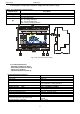
Enclosure dimensions 122 x 93 x 60 (WxHxD) [mm] (+/- 2)
Mounting TH35 DIN rail
Net/gross weight
0,45 kg/ 0,52 kg
Enclosure ABS, RAL9003, white
Connectors Φ0,51-2,05 (AWG 24-12)
Safety of use (Table 4)
Protection class PN-EN 60950-1:2007 I (first)
Protection grade PN-EN 60529: 2002 (U) IP20
Insulation electrical strength:
- between input (network) circuit and the output circuits of the PSU (I/P-O/P)
- between input circuit and PE protection circuit (I/P-FG)
- between output circuit and PE protection circuit (O/P-FG)
3000 V/AC min.
1500 V/AC min.
500 V/AC min.
Insulation resistance:
- between input circuit and output circuit
100 MΩ, 500V/DC
Operation parameters (Table 5)
Environmental class II
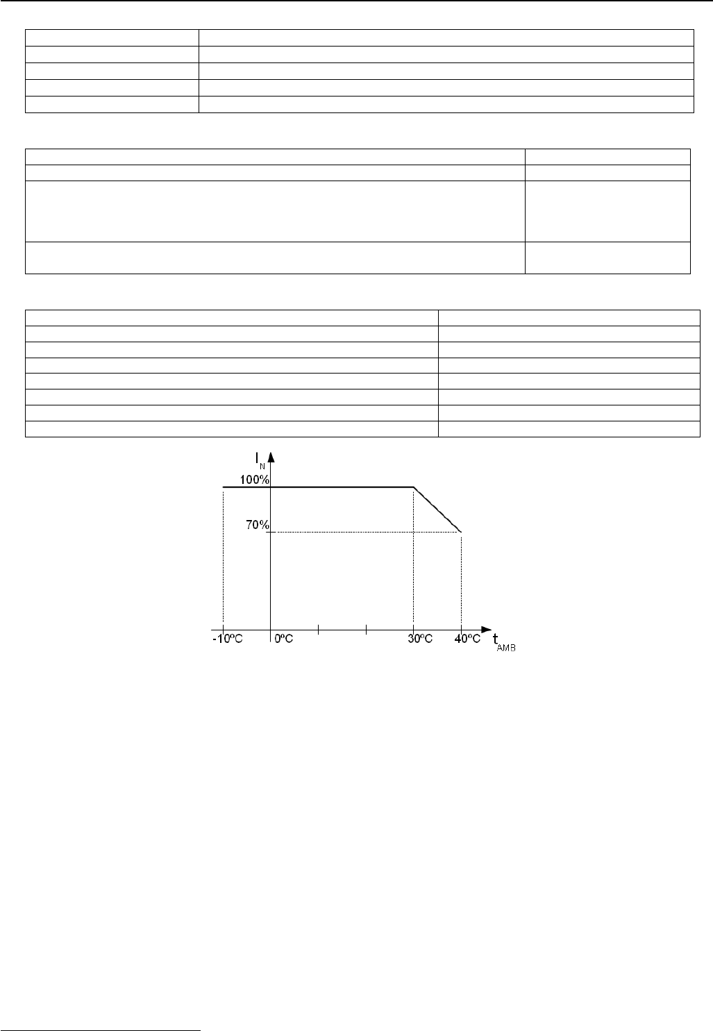
Operating temperature -10ºC...+40ºC
Storing temperature -25ºC...+60ºC
Relative humidity 20%...90%, no condensation
Sinusoidal vibrations during operation unacceptable
Surges during operation unacceptable
Direct insolation unacceptable
Vibrations and surges during transport compliant with the PN-83/T-42106
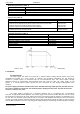
Chart 1. Acceptable output current from the PSU depending on ambient temperature.
2. Installation.
2.1 Requirements.
The power supply unit should be mounted by a qualified installer, holding relevant permits and licenses
(applicable and required for a given country) for 230V/AC and low-voltage installations. The unit should be
mounted in confined spaces, in accordance with the 2nd environmental class, with normal relative humidity
(RH=90% maximum, no condensation) and temperature range from -10°C up to +40°C. The power supply sh ould
operate in a vertical position in order to provide free and convectional air flow through ventilating holes of the
enclosure
The power supply load balance should be done before installation. During normal operation, the total current of
the receivers should not exceed I=5A. The maximum battery charging current is 0.5A. The total current of the
receivers + battery is max. 5.5A
*
.
The power supply is designed for a continuous operation and is not equipped with a power-switch.
Therefore, an appropriate overload protection in the power supply circuit should be provided. Moreover, the user should
be informed how to disconnect the power supply unit from the mains supply (usually by assigning an appropriate fuse in
the fuse box). The electrical system shall be made in accordance with applicable standards and The unit should be
mounted in a metallic enclosure (telecommunication cabinet) fitted with TH35 DIN rail (35 mm width); in order to meet the
LVD and EMC requirements, the rules concerning power supply, building-in and shielding should be followed accordingly.
*
Refer to chart 1