
User Instructions

3
1.3. Technical parameters:
- Electrical parameters (Table 3)
- Mechanical parameters (Table 4)
Table 3.
The input voltage range (power supply)
8V÷28V DC
depending on the range set by the jumper
The output voltage range
4,5V÷7V, 7V÷10V, 10V÷15V, 15V÷24V
Jumper adjustable.
Factory setting: 12V.
The minimum difference between the input and
output voltage
2V
P module power
60W max. (see fig.3)
Energy efficiency
85%÷ 92%
Ripple voltage
80mV p-p max
Output current
5A max. (see fig.3)
Current consumption by module systems
20 mA max.
Short-circuit protection SCP
electronic, automatic recovery
Overload protection OLP
110-150% of the module’s power, manual restart (the failure
requires disconnection of the DC output circuit)
Technical outputs
- PSU output indicating failure – overload or short-
circuit in the AUX output
- OC type, 50mA max. Failure status: hi-Z state (high
impedance), normal status: L level (0V)
Optical indication
- IN LED indicating DC power status
- AUX LED indicating DC supply status at the output
- PSU LED indicating failure - overload or short-
circuit in the AUX output
- red, normal status: is lit continuously
- green, normal status: is lit continuously
- red, normal status: does not lit, failure: is lit continuously
Operating conditions
II environmental class, -10°C ÷40°C, ensure air flow around
the unit for convection cooling
Declarations, Warranties
CE, 2 years from the production date
Table 4.
Dimensions
L=140, W=43, H=45 [+/- 2mm]
Mounting
tape or mounting screw x 2
Terminals
Ф0,41÷1,63 (AWG 26-14)
Net/gross weight
0,15/0,20 kg
2. Installation.
2.1. Requirements.
The DC/DC converter is to be mounted by a qualified installer, holding relevant permits and licenses (applicable and required
for a given country) for step down installations. The module should be mounted in confined spaces with normal relative humidity
(RH=90% maximum, no condensation) and temperature range from -10°C up to +40°C. The module should operate in vertical position
in order to provide free and convectional air flow.
Proper operation of the module requires adequate current capacity of the power source; the power supply capacity should be
calculated using the formula below:
PIN = 1,15 x PAUX
(PIN = 1,15 x IAUX x UAUX)
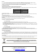
The module's load balance should be
done prior to installation. During normal
operation, the total current of the receivers should
not exceed I=5A while the power drawn from the
module should not exceed Pmax=60W, as shown
in the Fig. 3.
Fig.3. The maximum output current
depending on the output voltage.