
User Instructions
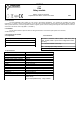

AWZ515
v.1.0
PK4
Relay module
Edition: 4 from 01.03.2018
Supersedes the edition: 3 from 10.07.2013 EN
1. Intended use.
The PK4 (AWZ515) relay module is to be used in low-voltage installations. It is intended for controlling and status
indication in e.g. alarm or access control systems. It may be used to control devices of high power consumption via OC outputs of
alarm systems. Moreover, it ensures galvanic isolation of signals, power sources relating to the outputs of the module. It features a
serial fuse in the circuit of the relay (BELL+, SYGNAL+).
2. Installation.
The set also includes 4 spacers fi=6mm for fixing the module to a flat surface (side panel of an enclosure,
a buffer PSU, etc.).
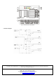
3. Description of the module.
3.1 Components. 3.2 Connectors.
4. Specifications.
SYGNAL +, SYGNAL-, BELL+, BELL -, WE AUX+, WE
AUX , PGM1, PGM2 - inputs of the voltage that control
the relay
C – common terminal of the relay
NO – normally open relay’s contact
NC – normally closed relay’s contact
1 – LED (indicates relay’s operations)
2 – fuse
3 – relay
4 – module terminals
Voltage of the relay’s coil
10÷14V DC (-/+5%),
Current of the relay’s coil
25mA@12VDC
Number of relays
4
Voltage of the relay’s contacts
30VDC / 50VAC max.
Current of the relay’s contacts
2A max.
Contacts of relay
C/NC/NO (leads Φ2.05 mm: AWG 24-12)
ON/OFF time
15ms/8ms (-/+5%)
Fuses
F1=2A, F2=0.5A
Operating conditions
2nd environmental class, -10°C÷ 40°C
Enclosure
open-frame design, IP00
Dimensions
L=75, W=70, H=20 [mm, +/-2]
Net/gross weight
0,06 / 0,09 [kg]
Installation
Mounting pins x 4
Declarations, warranty
CE, 2 year from the production date
Notes
leads on connections:Ø 0,41÷1,63
(AWG 26-14),
Ø 0,51÷2,05 (AWG 24-12) - relay contacts