
User Instructions

www.pulsar.pl AWZ100 GREY POWER
3
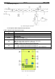
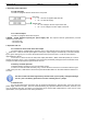
1.2 Block diagram (Fig. 1).
Fig. 1. Block diagram of the PSU.
1.3 Description of PSU components and connectors.
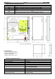
Table 1. Elements of the PSU pcb (see Fig. 2).
Element no.
Description
[1]
Connector: AC power supply input – factory setting
[2]
F
BAT
fuse in the battery circuit – F2A
[3]
P1 potentiometer, adjustable DC voltage in the range of 12V÷ 14,5V
[4], [5]
LED indication:
AC - LED for AC voltage
AUX - LED for DC output voltage
[6]
Connectors:
+BAT- DC supply output of the battery (+BAT= red, -BAT=black)
+AUX- DC supply output (+AUX= +U, -AUX=GND)
TAMPER - contacts of the sabotage protection switch (NC)
[7]
P
BAT
; pins - configuration of UVP battery protection function
P
BAT
= protection (disconnection) of the battery off
P
BAT
= protection (disconnection) of the battery on - page 7 section.4.2
[8]
START – button (launching the PSU from a battery) - page.7 section.4.2
Fig. 2. The view of the PSU pcb.