INSTALLATION OPERATION MAINTENANCE INSTRUCTION BULLETIN No. PS-IOM-SHD-0303-Rev C Manufacturers of Quality Pumps, Controls and Systems Engineered Pump Operations 2883 Brighton-Henrietta Townline Road Rochester, New York 14623 Telephone: (585) 292-8000 Fax: (585) 424-5619 http://www.pulsa.com pulsa@idexcorp.
i
PULSAR Factory Service Policy Should you experience a problem with your PULSAR pump, first consult the troubleshooting guide in your operation and maintenance manual. If the problem is not covered or cannot be solved, please contact your local Pulsafeeder Sales Representative, or our Technical Services Department for further assistance. You may also visit our website at www.pulsa.com Trained technicians are available to diagnose your problem and arrange a solution.
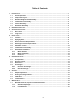
Table of Contents 1. INTRODUCTION .....................................................................................................................................1 1.1 Overall Operation ....................................................................................................................1 1.2 Component Layout..................................................................................................................2 1.3 Standard Reagent Head Assembly.................................
7.2 Check Valves ...........................................................................................................................22 7.2.1 General Description.........................................................................................................22 7.2.2 Removal, Inspection, and Reinstallation.......................................................................22 7.3 Oil Seals .......................................................................................................
Conventions: The following Conventions are used in this document. A WARNING DEFINES A CONDITION THAT COULD CAUSE DAMAGE TO BOTH THE EQUIPMENT AND THE PERSONNEL OPERATING IT. PAY CLOSE ATTENTION TO ANY WARNING. Notes are general information meant to make operating the equipment easier.
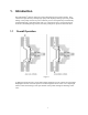
1. Introduction PULSAR Shadow® metering pumps are positive displacement reciprocating pumps. They combine the high efficiency of the plunger pump with diaphragm sealing to prevent product leakage. Each pump consists of a power end and a process end separated by a mechanically operated diaphragm. Individual pumps will vary in appearance due to various liquid ends, accessories, and multiplexing; however, the basic principles of operation remain the same. 1.
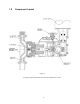
1.2 Component Layout Figure 2 A typical model with manual external stroke adjustment is shown.
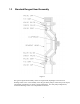
1.3 Standard Reagent Head Assembly Figure 3 The typical reagent head assembly consists of reagent head, diaphragm, and suction and discharge check valves. This assembly is the only part of the pump to contact the process liquid; consequently, maintenance is critical to pump performance. For most pump configurations, suction and discharge check valve components are identical.
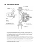
1.4 Leak Detection Assembly Figure 4 The Leak Detection Assembly (LDA) consists of a reagent head, suction and discharge check valves, primary diaphragm, leak detection diaphragm assembly, pressure switch port, and optional pressure switch and gauge. The reagent head, suction and discharge check valves, and primary diaphragm are the only parts of the pump to contact the process liquid; consequently, maintenance is critical to pump performance.
1.5 Control Assembly Figure 5 PULSAR Shadow® pumps incorporate a lost motion style of stroke length adjustment to limit diaphragm travel during the suction portion of each stroke. The stroke length setting is indicated by a (0 - 100) scale located on the top of the unit. Stroke length is changed by depressing and turning the hand knob. This turns a screw, which locates a wedge-shaped slider cam to position the follower pin, which in turn limits rearward travel of the diaphragm.
1.6 Gear Ratio Assembly Figure 6 PULSAR Shadow® pumps are driven by a standard C-face electric motor mounted on the motor adaptor input flange. The motor drives a set of worm gears, which convert rotational speed into torque. They, in turn, power the eccentric shaft assembly that converts rotary motion into reciprocating motion. The drive motor can be wired to rotate in either direction. More than one pump can be driven through a single drive assembly. This is referred to as multiplexing.
2. Equipment Inspection Check all equipment for completeness against the order and for any evidence of shipping damage. Shortages or damage should be reported immediately to the carrier and your authorized representative for PULSAR Shadow® pumps. 3. Storage Instructions 3.1 Short Term Storage of PULSAR Shadow® pumps for up to 12 months is considered short-term. The recommended short-term storage procedures are: 1. Store the pump indoors at room temperature in a dry environment. 2.
4. Installation 4.1 Location When selecting an installation site or designing a skid package, consideration should be given to access for routine maintenance. PULSAR Shadow® pumps are designed to operate indoors and outdoors, but it is desirable to provide a hood or covering for outdoor service. External heating is required if ambient temperatures below 0O C (32O F) are anticipated. Check with the factory if concerned with the suitability of the operating environment.
3. An inlet strainer, if the product is not a slurry. Pump check valves are susceptible to dirt and other solid contaminants unless designed for that service, and any accumulation can cause malfunction. The strainer should be located between the suction shutoff valve and the pump suction valve. It must be sized to accommodate the flow rate and the anticipated level of contamination. A 100-mesh screen size is recommended. 4.
4.5 Automatic Control Pumps equipped with the DLC, DLCM, or ECA electronic stroke length controllers are provided with separate instructions. Refer to the latest Installation, Operation and Maintenance Manual specific to your controller. Follow all safety and operational information contained in those documents. Perform and verify all controller installation procedures prior to pump startup.
4.6 Leak Detection Assembly Figure 10 If the diaphragm leak detection system was specified with an optional pressure switch, install electrical wiring and conduit in accordance with local electrical codes. The switch is rated as follows: The switch is rated as follows: 30 VDC or 125 VAC 1 Ampere Resistive. The switch should be wired such that if a leak condition is detected, the pump will be shut down.
4.7 4.7.1 Drive Motor Installation Motor Rotation Motor can be operated in either direction, clockwise or counterclockwise. Verification of motor direction is not necessary at startup. 4.7.2 Motor Installation PULSAR Shadow® pumps may be shipped with the drive motor packed separately. This is done to avoid damage during transport. Figure 11 1. Remove the unattached coupling half from the motor adaptor.
5. Equipment Startup PULSAR SHADOW® PUMP USE TWO SEPARATE OILS: PULSALUBE 9M OIL FOR THE ECCENTRIC BOX AND PULSALUBE 8G, GEAR OIL FOR THE GEARBOX. CONFUSION BETWEEN THE TWO REDUCES PERFORMANCE OF THE PUMP. 5.1 Oil Capacities Pulsalube 9M lubricating oil is available in 950 ml (1 quart) containers. Pulsalube 8G gear oil is available in 200 ml (.21 quarts) or 950 ml (1 quart) containers.
Figure 12 5.3 Gear Oil Fill In all pump configurations, one pipe plug is present at the top of the gearbox and one is on the side at the centerline level. Remove the top plug and fill with Pulsalube 8G gear oil through the top port to the level of the eccentric shaft centerline, which is level with the side port. The side plug should be removed so that leakage from the side port indicates attainment of the required level. Replace both pipe plugs after filling.
5.4.1 Eccentric Oil Change: The recommended eccentric oil change interval is two (2) years for normal service and one (1) year for severe service. The procedure is as follows: 1. 2. 3. 4. 5. Disconnect the power source to the drive motor Relieve all pressure from the piping system. Remove the top cover or controller from the pump. Drain the oil by removing the drain plug on the bottom of the eccentric box. Replace the drain plug. 6.
6. Startup 6.1 Output Adjustment Figure 13 PULSAR Shadow® pumps have a handwheel for manual stroke length adjustment. Mounted atop the eccentric box, the handwheel can be adjusted at any point from (0 to 100%) stroke setting by pressing down and then rotating as required. Stroke length is locked during operation to prevent drift: pressing the handwheel down temporarily disengages the lock for adjustment; release after adjustment automatically resets the lock at the new setting.
4. Start the pump at the zero stroke length setting and slowly increase the setting to 100 to prime the pump. If this does not work, it will be necessary to fill the suction line. 5. Filling of the suction line will necessitate the use of a foot valve or similar device at the end of the suction line so that liquid can be maintained above the reservoir level.
6.4 Leak Detection Figure 15 Follow the same priming procedure for a standard reagent for pumps equipped with the diaphragm leak detection system. If the optional pressure switch has been supplied, apply power to the alarm circuit. It is recommended that this switch be integrated into the pump control system. If a failure of the diaphragm is detected, the pump should be shut down until a diagnosis of the fault can be made.
7. Maintenance BEFORE PERFORMING ANY MAINTENANCE REQUIRING REAGENT HEAD OR VALVE (WET END) DISASSEMBLY, BE SURE TO RELIEVE PRESSURE FROM THE PIPING SYSTEM AND, WHERE HAZARDOUS PROCESS MATERIALS ARE INVOLVED, RENDER THE PUMP SAFE TO PERSONNEL AND THE ENVIRONMENT BY CLEANING AND CHEMICALLY NEUTRALIZING AS APPROPRIATE. WEAR PROTECTIVE CLOTHING AND EQUIPMENT AS REQUIRED. Accurate records from the early stages of pump operation will indicate the type and levels of required maintenance.
7.1.1 Standard Diaphragm Figure 16 PULSAR Shadow® diaphragms do not have a specific cycle life; however, the accumulation of foreign material or debris sufficient to deform the diaphragm can eventually cause failure. Failure can also occur as a result of system over pressure or chemical attack. Periodic diaphragm inspection and replacement are recommended. 1. Adjust the stroke setting to 50 percent and disconnect the power source to the drive motor 2. Relieve all pressure from the piping system. 3.
9. Remove the final bolt and rinse or clean the reagent head as required. 10. Remove the diaphragm by turning counter-clockwise and inspect the diaphragm. The diaphragm must be replaced if any surface is cracked, separated, or obviously damaged. 11. To install a diaphragm, first ensure that the critical sealing areas of diaphragm, reagent head, and pump head are clean and free of debris.
7.2 Check Valves 7.2.1 General Description Most fluid metering problems are related to check valves. Problems usually stem from solids accumulation between valve and seat, corrosion of seating surfaces, erosion, or physical damage due to wear or the presence of foreign objects. The valve incorporates a ball, guide, and seat. Flow in the unchecked direction lifts the ball off the seat, allowing liquid to pass through the guide.
10. Reassemble both valves using new parts as required. Sealing “O”-rings should generally be replaced. 11. Reinstall both valve assemblies, taking care to ensure that they are correctly oriented with balls above seats. 12. Tighten the tiebar bolts evenly, making sure the valve assemblies are assembled squarely. Refer to Appendix III for torque values. 13. Check for leaks and retighten tiebar bolts as necessary. Re-check any piping connections that may have been disturbed. Figure 18 7.3 Oil Seals 7.
7.5 Removal and Replacement To replace the pump shaft seal: Following the instructions in the previous sections, remove the reagent head assembly. Then remove the diaphragm. Remove the pump shaft by unscrewing counter-clockwise. Take care not to allow any shims to drop into the eccentric box when removing the shaft. A thread-locking compound is used between the pump shaft and the crosshead assembly. Remove the three (3) socket head screws and seal retainer plate. The seal can now be removed.
To replace the gearbox oil seal: First drain the gearbox per the lubrication instructions. Remove the four gearbox bolts, and withdraw the gearbox from the eccentric box, sliding it off the eccentric shaft. Remove the seal. Lubricate the replacement with Pulsalube 8G gear oil and install by pressing into position. Reinstall by reversing the disassembly procedure. Refill the gearbox with Pulsalube 8G gear oil per Lubrication. To replace the eccentric box seal: First remove the gearbox per step 3 above.
7.6 7.6.1 Cover Assembly Removal and Reinstallation Figure 21 The hand knob linkage employs a slip type coupling which can be reassembled in either of two rotational orientations 1800 apart from one another: therefore, the original orientation must be retained for reassembly so that pump calibration is retained. 7.6.2 Removal 1. Adjust the stroke length until the dial indicator is set at the zero stroke setting. Adjustment is easier with the drive motor running.
7.6.3 Reinstallation 1. Rotate the stroke cam screw clockwise until the slider cam is in a full upward position. 2. Verify that the cover dial indicates the zero stroke setting. 3. Using care not to disturb the adjustment shaft, install the cover assembly, engaging the drive coupling. 4. Replace the cover screws. 5. Press the adjustment knob down and rotate it clockwise until it stops. (Adjustment is easier with the drive motor running.
8. Replacement Parts 8.1 PULSAR Shadow® KOPkit Program Figure 22 PULSAR Shadow® KOPkits contain all replacement parts normally used in a preventative maintenance program. Having a KOPkit on hand can eliminate delays in repairing a pump and returning it to a critical service. Pulsalube 9M eccentric oil and Pulsalube 8G gear oils are also available for preventative maintenance programs, and should be kept on hand. There is a specific KOPkit for every PULSAR Shadow® pump model.
This page intentionally left blank 29
9. Troubleshooting Chart Difficulty Probable Cause Remedy Pump does not start. 1. Coupling disconnected. 2. Faulty power source. 3. Blown fuse, and circuit breaker. 4. Broken wire. 5. Wired improperly. 6. Pipe line blockage. Connect coupling. Check power source. Replace - eliminate overload. Locate and repair. Check diagram. Open valves. No delivery. 1. Motor not running. 2. Supply tank empty. 3. Lines clogged. 4. Closed line valves. 5. Ball check valves held open with solids. 6.
Troubleshooting Chart (cont.) Difficulty Probable Cause Remedy Pump loses internal oil 1. Diaphragm ruptured. 2. Leaky seal. 3. Cover gasket leaks. 5. Pump overfilled. Replace. Replace. Replace or retighten. Remove excess oil. Noisy gearing, knocking 1. Discharge pressure too high. 2. Water hammer. 4. Stroke length at partial setting. Reduce pressure. Install pulsation dampener. Nondestructive knocking is characteristic of lost motion pumps. Replace or refill oil 5.
10. APPENDIX I Piping Calculations 10.1 Suction Head Requirements All reciprocating metering pumps require a net positive suction head (NPSHR). The NPSHR for PULSAR Shadow® pumps is 5 psi (0.35 bar). The NPSHR is defined as the pressure required above the absolute vapor pressure of the process fluid at the pumping temperature. This pressure is required at the suction port of the pump throughout the entire pump stroking cycle in order to prevent cavitation of the process fluid within the reagent head.
10.2 System Backpressure The system backpressure must exceed the suction pressure by at least 5 psi (0.35 bar) in order to prevent flowthrough, however it must not exceed the rated discharge pressure of the pump. Flowthrough can be defined as the process liquid flowing from a higher pressure to a lower pressure (downhill pumping), which results in a flow output greater than the pumps calibrated capacity, failure and undesired flow at pump shutdown. If the system backpressure is not at least 5 psi (0.
11. APPENDIX II Oil Specifications PULSAlube #8G AGMA Number = 7 EP ISO Viscosity Grade = 460 API Gravity (ASTM D 287) = 34.
12. APPENDIX III Bolt Torque Tables PULSAR- Liquid End Bolt Torque Requirements Metal Construction Reagent Head Part # NP160001 NP160002 NP160003 NP160004 Head Size A B C D Head Bolts # Bolts and Size Torque N-m Ft-Lbs (6) M10 * 1.5 39 29 (6) M12 * 1.75 68 50 (6) M10 * 1.5 39 29 (6) M8 * 1.25 20 15 Tie Bars #Bolts and Size Torque N-m Ft-Lbs (4) M8 * 1.25 8 6 (4) M8 * 1.25 8 6 (4) M8 * 1.25 8 6 (4) M8 * 1.25 8 6 Head Bolts # Bolts and Size Torque N-cm in-lbs (6) M10 * 1.5 850 75 (6) M12 * 1.
13. Appendix V Pulsafeeder Accessories 13.1 Pulsation Dampeners The PULSuppressor pulsation dampener is a pneumatically charged diaphragm-type chamber that intermittently stores energy. Used on the inlet, it can improve NPSHa (Net Positive Suction Head available) characteristics of the suction piping system. On the discharge line it will reduce peak pressures and pulsating flow variations. Figure 23 13.
A) Discharge Setup The pulsation dampener may be precharged with air or nitrogen. When properly precharged the diaphragm is positioned against the bottom liquid chamber. It is therefore necessary to drain all liquid below the diaphragm and vent to atmospheric pressure when precharging. Use the precharge pressure as determined from the pulsation dampener selection and sizing procedure (Catalog No. 211). This can vary from 50 to 80% of mean line pressure in accordance with fluctuation level selected.
13.3 Pulsation Dampener Removal When removing or disassembling a pulsation dampener, drain all piping and remove all air and process pressure. Assume that the diaphragm is broken and the chamber is flooded under pressure since the pressure gauge could be damaged. Separate chambers with caution in a direction away from the body. REMEMBER THAT THE PULSATION DAMPENER HOUSING WILL RETAIN SOME AMOUNT OF PROCESS FLUID, AND HANDLE ACCORDINGLY. 13.
39
40
41
Engineered Pump Operations 2 8 8 3 B r i g h t o n - H e n r i e t t a T o wn l i n e R o a d Rochester, NY 14623 Telephone (585) 292-8000 Fax (585) 424-5619 pulsa@idexcorp.com h t t p : / / w w w. p u l s a .