Installation Operation Maintenance Instruction Bulletin #: PR – IOM – 0802 - D Hydraulic Diaphragm Metering Pump
PULSAR Factory Service Policy Should you experience a problem with your PULSAR pump, first consult the troubleshooting guide in your operation and maintenance manual. If the problem is not covered or cannot be solved, please contact your local Pulsafeeder Sales Representative, or our Technical Services Department for further assistance. Trained technicians are available to diagnose your problem and arrange a solution.
Table of Contents 1. INTRODUCTION ..................................................................................................................................... 1 1.1 General Description ................................................................................................................ 1 2. PRINCIPLES OF OPERATION.................................................................................................................. 1 2.1 Overall Operation ......................................
7.4.1 General Description ........................................................................................................ 21 7.4.2 Check Valve Screen - Removal and Cleaning .............................................................. 21 7.4.3 HPV Removal and Replacement - A & B Pumphead Style .......................................... 22 7.4.4 HPV Removal and Replacement - C & D Pumphead Style .......................................... 23 7.5 Hydraulic Bypass Valve (HBV) .........................
Conventions: The following conventions are used in this document. A WARNING DEFINES A CONDITION THAT COULD CAUSE DAMAGE TO BOTH THE EQUIPMENT AND THE PERSONNEL OPERATING IT. PAY CLOSE ATTENTION TO ANY WARNING. Notes are general information meant to make operating the equipment easier.
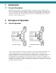
1. Introduction 1.1 General Description PULSAR metering pumps are positive displacement reciprocating pumps. They combine the high efficiency of the plunger pump with diaphragm sealing to prevent product leakage. Each pump consists of a power end and a process end separated by a hydraulically operated diaphragm. Individual pumps will vary in appearance due to various liquid ends, accessories, and multiplexing; however, the basic principles of operation remain the same. 2. Principles Of Operation 2.
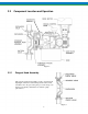
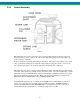
2.2 Component Location and Operation Figure 2 2.2.1 Reagent Head Assembly The typical reagent head assembly consists of reagent head, diaphragm, and suction and discharge check valves. This assembly is the only part of the pump to contact the process liquid; consequently, maintenance is critical to pump performance.
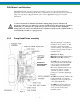
PULSAlarm Leak Detection The PULSAlarm leak detection reagent head assembly consists of reagent head, leak detection diaphragm, suction and discharge check valves, vacuum bleed port, and optional pressure switch and gauge. If your pump is equipped with this option, refer to Appendix I on page 33 for further information. A sealed system must be maintained at all times during pump operation, whether leak detection is required or not. If the proper level of vacuum, between 10 in and 26 in.
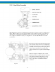
2.2.3 Control Assembly Figure 5 PULSAR pumps incorporate a lost motion style of stroke length adjustment to limit piston travel during the suction portion of each stroke. The stroke length setting is denoted by a (0 - 100) scale located on the top of the unit. Stroke is changed by depressing and turning the hand knob. This turns a screw which locates a slider cam to position the follower pin as to limit the rearward travel of the piston.
2.2.5 Gear Ratio Assembly Figure 6 PULSAR pumps are driven by a standard C-face electric motor mounted on the motor adaptor input flange. The motor drives a set of worm gears which convert rotational speed into torque. They in turn power the eccentric shaft assembly that converts rotary motion to reciprocating motion. The motor adaptor is available in a variety of configurations to accommodate different motor frame specifications. More than one pump can be driven through a single drive assembly.
3. Equipment Inspection Check all equipment for completeness against the order and for any evidence of shipping damage. Shortages or damage should be reported immediately to the carrier and your Pulsafeeder representative. 3.1 3.1.1 Storage Instructions Short Term Storage of PULSAR pumps for up to 12 months is considered short-term. The recommended shortterm storage procedures are: a) Store the pump indoors at room temperature in a dry environment.
4.2 Piping System All piping systems should include: 1. Shutoff valves and unions (or flanges) on suction and discharge piping. This permits check valve inspection without draining long runs of piping. Shutoff valves should be of the same size as connecting pipe. Ball valves are preferred since they offer minimum flow restriction. 2. An inlet strainer, if the product is not a slurry.
4.3 Suction Pressure Requirements Although PULSAR metering pumps have suction lift capability, all pump installations should have minimum lift for optimum performance. A flooded suction (i.e., suction pressure higher than atmospheric pressure) is preferable whenever possible. The pump should be located as close as possible to the suction side reservoir or other source. Piping should be sized to allow for best possible NPSH conditions.
4.6 PULSAlarm Leak Detection Electrical Connections Pressure Gauge Figure 9 If equipped with an optional vacuum or pressure switch, install electrical wiring and conduit in accordance with local electrical codes. The switch is rated as follows: 30 VDC or 125 VAC 1 Ampere Resistive. The switch is the SPDT (single pole, double throw) type and can therefore be connected to either open or to close upon detection of diaphragm leak condition.
5. Equipment Setup 5.1 Lubrication PULSAR pumps use two separate oils: PULSAlube 7H, hydraulic oil for the eccentric box and PULSAlube 8G, gear oil for the gearbox. Confusion between the two will impair performance and damage the pump. PULSAR pumps are shipped from the factory with the Eccentric Housing drained, and the Gearbox full. The Installer should fill the Eccentric Housing. The external gearcase does not need to be checked. 5.1.
5.1.3 Hydraulic Oil Fill Remove the diagnostic window to gain access to the reservoir and add PULSAlube 7H hydraulic oil until the oil level is between the max and min as indicated on the new (flexible style) dipstick as illustrated below. For older pumps equipped with a solid dipstick, the oil level should be below the upper coils of the piston return spring, if the upper coils of the spring are submerged, the oil level is too high (ref. Figure 10). Adding 1 liter (approx.
Drive Motor Installation 5.2.1 Motor Rotation Motor can be operated in either direction, clockwise or counterclockwise. Verification of motor direction is not necessary at startup. 5.2.2 Motor Installation PULSAR pumps may be shipped with the drive motor packed separately. This is done to avoid damage during transport. Figure 11 1. Remove the unattached coupling half from the motor adaptor.
6. Startup Procedure 6.1 Output Adjustment Figure 12 All PULSAR pumps have a hand-wheel for manual stroke length adjustment. Mounted atop the eccentric box, the hand-wheel can be adjusted at any point (from 0 to 100% stroke setting) by pressing down and then rotating the hand wheel as required. Stroke length is locked during operation to prevent drift: pressing the hand-wheel down temporarily disengages the lock for adjustment; release after adjustment automatically resets the lock at the new setting.
6.2 Suction System Before operation of any PULSAR pump, carefully ensure that all suction valves are in the open position. Verify that all filters and strainers are clean and clear. Ensure that any other potential causes of restriction have been addressed. Unrestricted flow of liquid to the suction side of the pump is critical to proper operation. 6.3 Priming the Pumphead (Hydraulic System) All pumps are shipped with a fully primed hydraulic system.
6.5 Calibration Figure 13 All metering pumps must be calibrated in order to accurately specify stroke length settings for required flow rates. For pumps provided with DLC or DLCM electronic stoke length control, refer to separate instructions as noted on page 8. A typical calibration chart is shown in Figure 13.
6.
7. Maintenance BEFORE PERFORMING ANY MAINTENANCE REQUIRING REAGENT HEAD OR VALVE (WET END) DISASSEMBLY, BE SURE TO RELIEVE PRESSURE FROM THE PIPING SYSTEM AND, WHERE HAZARDOUS PROCESS MATERIALS ARE INVOLVED, RENDER THE PUMP SAFE TO PERSONNEL AND THE ENVIRONMENT BY CLEANING AND CHEMICALLY NEUTRALIZING AS APPROPRIATE. WEAR PROTECTIVE CLOTHING AND EQUIPMENT AS APPROPRIATE. Accurate records from the early stages of pump operation will indicate the type and levels of required maintenance.
7.1.2 Hydraulic Oil Change: The recommended hydraulic oil change interval is 2 years for normal service and 1 year for severe service. Hydraulic Oil change procedure is as follows: 1. 2. 3. 4. 5. Disconnect the power source to the drive motor. Relieve all pressure from the piping system. Remove the diagnostic window from the top of the eccentric box. Drain the oil by removing the drain plug on the bottom of the eccentric box.
7.2.1 Standard Diaphragm Replacement Figure 14 PULSAR diaphragms do not have a specific cycle life; however, the accumulation of foreign material or the entrapment of sharp particles between the diaphragm and dish cavity can eventually cause failure. Failure can also occur as a result of hydraulic system malfunction or chemical attack. Periodic diaphragm inspection and replacement are recommended. Diaphragm Replacement Procedure: 1. 2. 3. 4. 5. 6. 7. 8. 9. 10. 11. 12. 13.
7.2.2 Re-Priming the Pumphead HYDRAULIC PERFORMANCE VALVE (HPV) Leak Detection diaphragm systems require special hydraulic priming considerations to protect the diaphragm from damage during initial pump startup. Refer to Appendix I, page 33 and review these procedures carefully before restarting a PULSAR pump equipped with a leak detection system. Figure 15 Hydraulic Priming Procedure, for standard Composite (THY) and Solid (PTFE) diaphragms: 1. Disconnect the power source to the drive motor. 2.
7.3 Check Valves 7.3.1 General Description Most fluid metering problems are related to check valves. Problems usually stem from solids accumulation between valve and seat, corrosion of seating surfaces, erosion, or physical damage due to wear or the presence of foreign objects. The valve incorporates a ball, guide, and seat. Flow in the unchecked direction lifts the ball off the seat, allowing liquid to pass through the guide.
7.4 Hydraulic Performance Valve (HPV) 7.4.1 General Description During normal pump operation hydraulic fluid is continually discharged through the automatic bleed valve and may also be lost past the piston seals. This causes the diaphragm to be drawn further back on each successive suction stroke until it actuates the HPV. Once the valve is actuated, oil is allowed to flow into the hydraulic system until the piston reaches the end of the suction stroke.
7.4.3 HPV Removal and Replacement - A & B Pumphead Style Use the following procedure for a HPV Removal and Replacement (A & B Pumphead Style) 1. Remove the reagent head and diaphragm, and drain hydraulic oil from the eccentric box. 2. Remove the four bolts on the front eccentric box flange which retain the pumphead. The piston return spring is under compression and will force the pumphead/cylinder away from the eccentric box as the bolts are removed. 3.
12. Make certain that the diagnostics seal at the top of the eccentric box flange and the HPV feed port oring at the bottom of the flange are in place (refer to Figure 4). 13. Insert the pumphead into the eccentric box using the locating pins as a guide. 14. Some compression of the piston return spring will be required in order to start the pumphead retaining bolts after which the bolts can be tightened to complete installation of the head.
9. Inspect the o-ring on the cylinder locating shoulder for nicks or other damage and replace if necessary, lubricate with PULSAlube 7H. 10. Make certain that the diagnostics seal at the top of the eccentric box flange and the HPV feed port oring at the bottom of the flange are in place (refer to Figure 4). 11. Insert the pumphead onto the eccentric box using the locating pins as a guide. 12.
close to the pump as possible. With the pump operating at maximum stroke length, gradually increase the discharge pressure and observe when the HBV starts to operate. The cracking pressure of the valve must be at least as high as the maximum pressure of the system but no more than 10% over the pump’s rated pressure. After adjustment tighten the lock nut and reinstall the plastic cover. Periodic inspection of the valve seat is recommended.
7.7 Piston Seal Figure 21 7.7.1 Figure 22 General Description The piston seals are of carbon graphite reinforced TFE U-cup construction with a stainless steel energizer spring. The seal is mounted two different ways: on the piston (for the larger piston sizes – Figure 22) or in the cylinder (for the smaller piston sizes – Figure 21). With oil changes at recommended intervals, piston seals should give years of service. 7.7.2 Removal Use the following procedure to remove the Piston Seal: 1.
7.8 Oil Seals 7.8.1 General Description The pump has three oil seals as follows: Motor Adapter Seal Gearbox Oil Seal Eccentric Box Seal 7.8.2 – – – Inside the motor adapter, below the worm shaft coupling. Inside the end play adjustment cap on the side of the gearbox. Surrounding the eccentric shaft, where it protrudes from the box. Removal and Replacement Use the following procedure to remove and replace the motor adaptor seal: 1. Remove the motor. 2.
7.9 7.9.1 Cover Assembly Removal & Reinstallation Figure 23 The hand knob linkage employs a slip type coupling which can be reassembled in either of two rotational orientations 180° apart from one another: therefore, the original orientation must be retained for reassembly so that pump calibration is retained. Use the following procedure to remove the cover assembly: 1. Adjust the stroke length until the dial indicator is set at the zero stroke setting. Adjustment is easier with the drive motor running.
8. Pump Motor 8.1 Removal & Reinstallation Use the following procedure to remove and reinstall the pump motor: 1. Disconnect the power source to the drive motor. 2. Disconnect the motor wiring from the motor. 3. Remove the four bolts retaining the motor to the motor adaptor and remove the motor. The coupling is an interlocking jaw design and uses an elastomer spider between the two coupling halves.
10. Troubleshooting Chart Difficulty Probable Cause Remedy Pump does not start. 1. Coupling disconnected. 2. Faulty power source. 3. Blown fuse, and circuit breaker. 4. Broken wire. 5. Wired improperly. 6. Pipe line blockage. Connect coupling. Check power source. Replace - eliminate overload. Locate and repair. Check diagram. Open valves. No delivery. 1. Motor not running. 2. Supply tank empty. 3. Lines clogged. 4. Closed line valves. 5. Ball check valves held open with solids. 6.
Troubleshooting Chart (cont.) Difficulty Probable Cause Remedy Pump loses hydraulic oil. 1. Diaphragm ruptured. 2. Leaky seal. 3. Cover gasket leaks. 4. Pump head gasket leaks. Replace. Replace. Replace or retighten. Replace - tighten pump head bolts. Apply sealing compound. Remove excess oil. 5. Pump head overfilled. Air bleeds continuously from PTP (automatic bleed valve) 1. Hydraulic oil level low. 2. Hydraulic bypass valve operating each stroke. 3. Suction pressure too low. 4.
10.1 Diagnosis of Diaphragm Failure The following guide provides some potential causes of diaphragm failure; it is based upon visual observation of the diaphragm. Careful observation of both the pump and the surrounding system is necessary for proper diagnosis. This is only a guide, and may not include all potential causal factors.
11. Appendix I PULSAlarm Leak Detection System 11.1 PULSAlarm Leak Detection Reagent Head Assembly The PULSAlarm leak detection reagent head assembly consists of reagent head, leak detection diaphragm, suction and discharge check valves, vacuum bleed port, and optional pressure/vacuum switch and gauge.
11.3 Leak Detection Option – Setup for Vacuum A vacuum must be maintained at all times during pump operation, otherwise, the diaphragm halves may separate during the suction stroke of the pump, reducing flow capacity and potentially damaging the diaphragm. Pumps incorporating the leak detection option are shipped from the factory with the system evacuated to the operating vacuum of 650 mm Hg (26 in. Hg).
11.5 Pressure System Set-up and Priming If the pressurized leak detection system is opened to the atmosphere during maintenance or inspection, the system must be re-primed properly to avoid diaphragm damage and ensure proper leak detection operation and system performance. The standard factory intermediate fluid is a Silicone oil. If any other customer-specified media is used, it must be compatible with the materials of construction.
9. Empty the fill tube of fluid, and place it on the fitting near the switch, extending upwards, open to the atmosphere. 10. Ensure that the eccentric box of the pump has been filled to the appropriate level with the correct (normally Pulsalube 7H™) hydraulic fluid. 11. Adjust the pump to the zero stroke (0%) position. 12. If the pump is not already hydraulically primed, remove the PTP valve from the top of the pump head.
11.6 Leak Detection System Maintenance Although the PULSAlarm leak detection system requires minimal maintenance, vacuum must be maintained to prevent false alarms and diaphragm damage. 11.6.1 Vacuum Setpoint Adjustment If the optional switch is purchased, it is factory preset at the specified vacuum setpoint, 150 mm Hg (6 in. Hg), at which loss of vacuum causes the vacuum switch to actuate. The standard pressure switch is set to actuate at 5 psig.
11.7 PULSAlarm Leak Detection Diaphragm Maintenance After diaphragm failure, pressurized process fluid can be present in any part of the PULSAlarm leak detection vacuum system. Take appropriate precautions and handle with care. Figure 27 11.7.1 Leak Detection Diaphragm Removal Use the following procedure to remove the Leak Detection Diaphragm: 1. 2. 3. 4. 5. 6. 7. 8. 9. 10. 11. Disconnect the power source to the drive motor.
11.7.2 Inspection Remove and inspect the diaphragm assembly. It may have taken a permanent convex/concave set as a result of normal flexure and conformance to the dish-plate. This condition is normal and is not cause for replacement. The diaphragm must be replaced if it is deformed, dimpled, or obviously damaged. If the diaphragms have been removed from the spacer ring, the entire assembly should be replaced to ensure proper sealing of its components. 11.7.3 Leak Detection Diaphragm Reinstallation 1.
12. Appendix II Piping Calculations Suction Head Requirements All reciprocating metering pumps require a net positive suction head (NPSHR). Refer to Table 1 for the (NPSHR) required for PULSAR pump models. The NPSHR is defined as the pressure required above the absolute vapor pressure of the process fluid at the pumping temperature.
Table 2. Unit sets and constant values for use in NPSH Equations. Variable NPSH PA PH PV LS R G Q d µ LD PT PP VP C1 C2 C3 Units Set English Metric psi psia psi psia feet strokes/min no units gallons/hr inches centipoise feet psi psi feet/sec 24,600 45,700 46.8 bar bar(a) bar bar(a) meters strokes/min no units liters/hr millimeters centipoise Meters bar bar meters/sec 640 1.84 0.
System Back Pressure The system backpressure must exceed the suction pressure by at least 5 psi (0.35 bar) in order to prevent flow through, however it must not exceed the rated discharge pressure of the pump. Flow through can be defined as the process liquid flowing from a higher pressure to a lower pressure (downhill pumping), which attributes to pump failure and undesired flow at pump shutdown. If the system backpressure is not at least 5 psi (0.
13. Appendix III Oil Specifications PULSAlube # 7H API Gravity (ASTM D 287) = 31 Viscosity (ASTM D 2161) SSU @ 100° F = 175 Viscosity (ASTM D 2161) SSU @ 210° F = 51 Viscosity Index (ASTM D 2270) = 193 Pour Point (ASTM D 97) Degrees F (C) = -60(-51) Flash Point, COC (ASTM D 92) Degrees F (C) = 367(186) Fire Point, COC (ASTM D 92) Degrees F (C) = 403(205) Color = purple PULSAlube # 8G AGMA Number = 7 EP ISO Viscosity Grade = 460 API Gravity (ASTM D 287) = 34.
14. Appendix IV Bolt Torque Recommendations Metal Construction Reagent Head Part No. NP160001 NP160002 NP160003 NP160004 Head Size A B C D Head Bolts Torque No. Bolts & Size N-m Ft–lbs. (6) M10 * 1.5 39 29 (6) M12 * 1.75 68 50 (6) M10 * 1.5 39 29 (6) M8 * 1.25 20 15 Tie bar Bolts Torque No. Bolts & Size N-m Ft–lbs. (4) M8 * 1.25 8 6 (4) M8 * 1.25 8 6 (4) M8 * 1.25 8 6 (4) M8 * 1.25 8 6 Head Bolts Torque No. Bolts & Size N-cm In–lbs. (6) M10 * 1.5 850 75 (6) M12 * 1.75 850 75 (6) M10 * 1.
Installation On both discharge and suction lines, it is desirable to mount the PULSAtrol as close to the pump connection as possible. It can be mounted in any position: horizontally, vertically, or at any angle. A shutoff valve should always be used between the piping system and PULSAtrol. If the discharge line is open to atmospheric pressure, a backpressure valve should also be incorporated in the system near the PULSAtrol to assure proper operation.
PULSAtrol Removal When removing or disassembling a PULSAtrol, drain all piping and remove all air and process pressure. Assume that the diaphragm is broken and the chamber is flooded under pressure since the pressure gauge could be damaged. Separate chambers with caution in a direction away from the body. Back Pressure Valve Figure 29 The Pulsafeeder diaphragm backpressure valve creates constant backpressure.
47
12 - 2006 Bulletin PR-IOM-0802 Rev D