Installation, Operation & Maintenance Instruction ® PULSAR ECA NEMA Type 4X ELECTRONIC CONTROL ASSEMBLY IOM-CTL-2001-Rev E
ECA FACTORY SERVICE POLICY Your ECA is a state of the art microprocessor-based stroke length control device for use with PULSAR® Diaphragm Metering Pumps. If you are experiencing a problem with your ECA, consult the trouble-shooting guide. If the problem is not covered or cannot be solved, please contact your local PULSA Series Sales Organization or our Technical Service Department at (585) 292-8000 for further assistance. Trained individuals are available to diagnose your problem and arrange a solution.
Table of Contents 1. INTRODUCTION ................................................................................................................................ 1 2. FOREWORD ...................................................................................................................................... 1 2.1 Description ............................................................................................................................... 1 2.2 ECA Standard Features ..........................
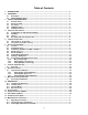
Conventions For the remainder of this bulletin, the following conventions are in effect. A WARNING DEFINES A CONDITION THAT COULD CAUSE DAMAGE TO BOTH THE EQUIPMENT AND THE PERSONNEL OPERATING IT. THIS MANUAL MUST BE CONSULTED IN ALL CASES WHERE THE WARNING SYMBOL IS MARKED IN ORDER TO FIND OUT THE NATURE OF THE POTENTIAL HAZARDS AND ANY ACTIONS WHICH HAVE TO BE TAKEN TO AVOID THEM. CAUTION, POSSIBILITY OF ELECTRIC SHOCK Notes are general information meant to make operating the equipment easier.
1. INTRODUCTION The ECA is a microprocessor based stroke length control device for use with the PULSAR diaphragm-metering pump. It has been designed to operate in a variety of industrial environments. This document describes the ECA controller only. The operation and maintenance of the PULSAR metering pump is covered in the pump IOM. Please refer to this IOM for important safety and operational instructions for your PULSAR pump. 2.
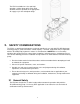
The ECA is available for 115 or 230 VAC operation, at either 50 or 60 Hz. Each ECA controller must be operated on the appropriate AC supply as per the nameplate ratings. 3. SAFETY CONSIDERATIONS The ECA is a sophisticated microprocessor based controller for use only with PULSAR diaphragm metering pumps. It yields tremendous control capacity -- electrical, mechanical and (in conjunction with the PULSAR pump) hydraulic in nature.
3.2 Electrical Safety The ECA can be considered an industrial process controller. Improper application and use can be hazardous. You are solely responsible for its use. The ECA’s electrical installation must conform to all local, state and national relevant electrical codes. Installation and electrical maintenance must be performed by a qualified electrician. Before installing or servicing this device, all power must be disconnected from the source at the main distribution panel.
Attempts to disassemble, modify or tamper in general by unauthorized personnel will void the guarantee and will release Pulsafeeder, Inc. from any liability for damage caused to persons or property resulting from such actions. Pulsafeeder, Inc.
4. TRANSPORT AND STORAGE 4.1 Consignment receipt and unpackaging Immediately after receipt of the equipment it must be checked against the delivery/shipping documents for its completeness and that there has been no damage in transportation. Check any crate, boxes or wrappings for any accessories or spare parts that may be packed separately with the equipment or attached to side walls of the box or equipment. Each product has a unique serial number.
5. STORAGE INSTRUCTIONS The ECA can be successfully stored for extended periods. The key to this success is control of temperature and humidity. 5.1 Short Term (0 - 12 months) The ECA should be stored in a temperature and humidity controlled environment. It is preferable to keep the temperature constant in the range of -18 to 40° Celsius (0 to 104° Fahrenheit). The relative humidity should be 0 to 90% non-condensing.
If the ECA is removed from the pump eccentric box, it should be stored in the same pump mounted orientation. After removing the ECA from the eccentric box, seal the opening with a dust and moisture proof material. If the ECA was shipped in its own carton, it should be stored in that carton. 5.2 Long Term (12 months or more) Storage of the ECA for periods of longer than twelve months is not recommended.
6. INSTALLATION AND WIRING 6.1 Location The site selected for the installation of your ECA is largely dependent on that of the PULSAR metering pump. Please review the PULSAR Installation Operation Review the Safety section prior to installing the ECA. It contains important information required to properly install and operate the ECA in industrial environments. Maintenance Instruction Manual (current version) provided with your PULSAR metering pump.
6.4 Housing Access All wiring and programming of the ECA must be accomplished through the removal of the housing cover. Use this procedure for removal and replacement: Cover Removal • Disconnect power at the source (follow your local Lock-Out-Tag-Out procedures). • Disconnect power at the source. • Loosen and remove the 4 Phillips head screws which secure the rear cover. • Grasp the cover and lift straight up.
1. 2. 3. 4. 5. 6. 7. Disconnect power at the source (follow your local Lock-out-Tag-out procedures). Verify that the mating surface of the lower half of the ECA is clean. Inspect the mating surface for any indication of damage or dirt. Position the cover and set in place. Insert and tighten the 4 phillips head screws. Return the ECA to the desired operating condition. Torque the 13 Socket Head Cap Screws to 100in-lb (11.3 N-m).
6.5 Electrical Wiring WHILE THE ECA WIRING REQUIREMENTS ARE VERY SIMPLE, ALWAYS KEEP IN MIND THAT ACCESS TO THESE CONNECTORS REQUIRES THE REMOVAL OF THE COVER, AND AS SUCH THIS PROCEDURE SHOULD ONLY BE PERFORMED BY A TRAINED PROFESSIONAL. Wait a minimum of 3 minutes after disconnecting power before servicing the ECA or pump motor. Capacitors retain a charge even after power is removed from the controller.
Recommended Minimum Wiring and Circuit Breaker Power Requirements ECA 115 VAC Operation 230 VAC Operation Actual Circuit Wire Wire Safety Draw Breaker 200ma 10A Size 14 AWG Size 2.5 2 mm Approvals UL, CUL, CE 1 Actual Circuit Wire Wire Safety Draw Breaker 200ma 10A Size 14 AWG Size 2.5 2 mm Approvals UL, CUL, CE Note 1: UL File E217212, Applicable standards are CSA 22.
Figure 3 – Earth grounding 13
Ref.
6.7 Labeling – Nameplate 6.8 Control Input and Output Connections 6.8.1 Motor Status Input The contactor or motor starter controlling the PULSAR motor should be equipped with a normally open auxiliary contact, which closes to indicate the PULSAR motor is on. This auxiliary contact, which must be an un-powered, dry contact only, is to be wired to inputs (J4-5 and J4-6) at the ECA, after removing the factory installed jumper wire. Remove approximately 0.
6.8.3 Analog Output (current loop) The Analog Output sends a signal representing the actual stroke length position. It can be adjusted to source current in the 0 to 25 mA range (4-20mA factory default). The output can also be set up for reverse-acting or split-ranging operation. The Current Output can be used to control slave devices (e.g. ECA’s, ELMA's, PULSAMATICs, etc.) or to fulfill closed loop system requirements. Use shielded cable (minimum 2conductor) for connection to the analog output.
7. START UP AND OPERATION 7.1 Overview Once all electrical connections have been made, your ECA is ready for Start-up. The following sections detail the procedures required to complete the ECA start up. WARNING: The ECA NEMA 4X Stroke controller includes a manual stroke control wheel. DO NOT OPERATE THIS MANUAL STROKE CONTROL WHEEL WHILE THE POWER TO THE STROKE CONTROLLER IS OFF. This will cause the electronics to error.
signal. Note that the minimum span, or difference between low and high values, is 2.0 mA. The ECA will not actuate to change stroke length during this process. THIS PROCEDURE REQUIRES REMOVAL OF THE ENCLOSURE COVER. THIS PROCEDURE SHOULD BE PERFORMED ONLY IF THE AREA IS KNOWN TO BE SAFE FOR ELECTRONIC WORK. • • • • • With the cover removed and power supplied to the ECA, press and release the white Input Cal pushbutton.
THIS PROCEDURE REQUIRES REMOVAL OF THE ENCLOSURE COVER. THIS SHOULD BE DONE ONLY IF THE AREA IS KNOWN TO SAFE FOR ELECTRONIC WORK. Figure 7 To calibrate the analog output, attach a milli-ammeter to the output circuit of the ECA in series with the PLC used to control the process (as shown in figure 7). It is recommended that you calibrate the ECA analog output values to whatever is required by the PLC.
• • • • • Press and hold the BLACK pushbutton Apply power to the ECA. A mechanical zero calibration routine will begin. The routine begins when the motor internal to the ECA starts motion looking for the zero position. Once the ECA begins the routine you may release the pushbutton. The calibration routine is complete when the motor reaches the zero position and the rotor locks for approximately 30 seconds. Zero calibration ends when the motor stops running. . Remove Power to the ECA.
• The Cal Output LED will blink a number of times to indicate the second trouble code digit. This sequence will repeat until the trouble condition is cleared.
10.2 Trouble Codes Code Description Action Clear error by cycling power. Encoder Error The CPU failed to read an encoder pulse, or has not received the expected signals in a certain amount of time. Thus, the controller has lost its zero reference. It then attempts to recover by doing a mechanical zero calibration. If the mechanical zero calibration is successful, this error is cleared, and normal operation continues.
10.3 Self-Test Mode The ECA has a diagnostic test mode which can be used to verify performance and troubleshoot problems. To initiate the self-test: • • Remove power from the ECA, and remove the top cover. Disconnect any field wires attached to J4, and connect Analog Out to Analog In. (jumper J4-1 to J4-3 and J4-2 to J4-4). • Press and hold the white Input Cal pushbutton. • Apply power to the ECA and release white Input Cal pushbutton.
Replace the cover and return power to the ECA. 10.4 Error Recovery In cases of abnormal operation, the following procedure is recommended: 1. First, check all power and process connections to ensure all wiring is secure and properly connected. 2. Check the internal connections within the ECA. 3. Ensure that the cable connections from the stroke adjustment motor and encoder are secure and seated properly. 4. Perform a Factory Re-initialization, as previously mentioned in this IOM.
11. SPECIFICATIONS 115 Volt/ 60Hz, 115 Volt/ 50Hz, 230 Volt/ 60 Hz, or 230 Volt/ 50Hz 200ma nominal, 2 amperes (short circuit) Input Power Input Current Stroke Length Control Stroke Adjustment response 0 – 100% control range Resolution – 0.0625% increments Approximately 1% per second Analog Input Operating Range Input Impedance Minimum Span Isolation Conditioning 0 to 25.5mA (4-20 mA factory default) 160 ohms 2.
Altitude: Humidity Temperature Earth Leakage Current Fuse Hz. Input frequency range 48 Hz to 62 Hz 3300 Ft (1000 M) above sea level (de-rate 5% per additional 3300 Ft) 0-90% (non-condensing) 0° C (32° F) Minimum operating temperature 40° C (104° F) Maximum operating temperature Size Earth Leakage Circuit Breakers (ELCB) to a detection level of 30 mA or greater One Power input fuse (AC over current protection) is located on the main control board. This fuse is a 2 amp slow-blow type (Schurter 34.
13.
14. TROUBLESHOOTING GUIDE Problem Potential Cause Solution INTERNAL LED DISPLAY No LED Display Normal, after setup. No action required No power supplied. Check power source. plug & circuit breaker Check wiring. Check voltage/frequency against specification. Adjust as per Start-up & Operation section See table in Diagnostics Trouble Code section for LED blink codes Supply power wired incorrectly. Supply power outside of specification.
15. MAINTENANCE & SPARE PARTS All maintenance work must be carried out only when the ECA and connected equipment is stopped and disconnected from mains supply (including auxiliary circuits). Maintaining original characteristics over time must be ensured by an efficient maintenance and inspection plan, developed and managed by qualified technicians, taking into account the service and the actual environmental conditions in which it operates. 15.
15.3 User Replaceable Parts for the ECA MFG & MFG P/N Schurter 34.
A unit of IDEX Corporation 2883 Brighton Henrietta Town Line Road Rochester NY 14623 +1 (585) 292-8000 pulsa.com pulsa@idexcorp.