
Owner's manual


120
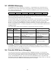
Notes:
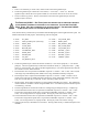
1. There is one character per 16-bit value, which resides in the least significant byte.
2. The most significant byte contains the cursor status (0 = cursor off, 1 = cursor on). The least
significant byte contains the cursor position offset (0-15 for the first line and 16-31 for the second).
3. Used to invoke Key-presses. The key value must be sent in the least significant byte (the most
significant byte is unused).
T
HIS
R
EGISTER
(0
X
0041 – K
EY
P
RESS
)
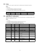
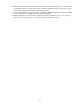
MUST NOT BE USED FOR AUTOMATION PURPOSES
.
IT CAN PRESENT HAZARDOUS CONDITIONS TO THE OPERATOR
. A
CTIVATING
C
ODE
0
X
01
(S
TOP
_S
TART
_K
EY
)
WILL OVERRIDE LOCAL KEYPAD CONTROL
! U
SE REGISTER
0
X
0042 -
P
UMP MOTOR STATUS FOR AUTOMATED MOTOR CONTROL
.
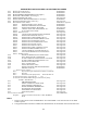
Note, that the UP Key and Down Key are inhibited from modifying the stroke length and motor speed. Use
0x0043 and 0x0044 for that purpose. The following codes are assigned:
0 = 0x00 = NO_KEY 10 = 0x0A = UP_ENTER_KEY
1 = 0x01 = STOP_START_KEY (motor key) 11 = 0x0B = DOWN_KEY
2 = 0x02 = MENU_KEY 12 = 0x0C = DN_REPEAT_KEY
3 = 0x03 = UNITS_KEY 13 = 0x0D = DN_ENTER_KEY
4 = 0x04 = BATCH_KEY 14 = 0x0E = UP_DOWN_KEY
5 = 0x05 = CALIBRATE_KEY 15 = 0x0F = SECRET_1_KEY
6 = 0x06 = MODE_KEY 16 = 0x10 = SECRET_2_KEY
7 = 0x07 = ENTER_KEY 17 = 0x11 = SECRET_3_KEY
8 = 0x08 = UP_KEY 18 = 0x12 = TIMEOUT_KEY
9 = 0x09 = UP_REPEAT_KEY
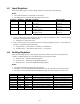
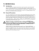
4. The most significant byte contains the desired condition (0 = user desires pump off, 1 = user desires
pump on). The least significant byte contains the actual motor status ( 0 = pump motor off, 1 = pump
motor on). When writing, only write to the Most Significant byte. The Least Significant byte must be
set to 0x00 or an error will be returned.
5. Percent-Stroke value is expressed in hundredths of percent i.e. 0x01F4 = 500 = 5.00%. The 0-10,000
value range may be modified by Ratio and Reverse Acting and further limited by end-points.
6. Percent-Speed value is expressed as hundredths of percent i.e. 0x2710 = 10000 = 100.00%. The 0-
10,000 value range may be modified by Ratio and Reverse Acting and further limited by end-points.
This value is write-able only in a DLCM. A DLC will always return 100.00%.
7. Stroke Counter 16-bits (Most significant or Least significant depending on register). The combination
of these addresses constitutes a 32-bit unsigned LONG value. It is useful only if the tachometer option
is installed (e.g., DLCM).
8. The least significant bit contains the Under/Over Voltage Flag (0=False[No Error], 1=True[Error]).
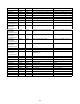
9. The Actual Stroke Position value is expressed in hundredths of percent i.e. 0x01F4 = 500 = 5.00%.
The Actual Average Motor Speed value is expressed in hundredths of percent i.e. 0x01F4 = 500 =
5.00%. The Average Interval is 10 pump strokes. Writing any value will reset the Average.
10. The Actual Stroke Position value is expressed in hundredths of percent i.e. 0x01F4 = 500 = 5.00%.
The Actual Average Motor Speed value is expressed in hundredths of percent i.e. 0x01F4 = 500 =
5.00%. The Average Interval is 10 pump strokes. Writing any value will reset the Average.
11. Writing while security is disabled sets a new PIN #. Writing while security is enabled compares to the
old PIN #.