
Manual


12
THE DLC-RC USES SOLID-STATE RELAYS FOR IT'S HIGH VOLTAGE OUTPUTS (I.E., MOTOR AND
ALARM
). IN THE 'OFF' STATE, THESE DEVICES TYPICALLY LEAK 20-30MA OF CURRENT AT
THE SUPPLY VOLTAGE
! THE SUPPLY POWER MUST BE DISCONNECTED AT THE MAIN BEFORE
WORKING ON ELECTRICAL CONNECTIONS
.
Wire the PULSAR motor to the motor starter in accordance with the starter manufacturer's
instructions. Alternately, the three-phase logic output may be used for most solid-state relay control
devices. See the Low Voltage Output, Three-Phase Solid State Relay sub-title in this Section for
more information. Double check all connections to confirm good electrical contact between the
terminal block clamp and bare wire. Make sure the clamp is on the wire, not the insulation. Insure
that bare wire is not frayed and does not rise above dividers.
5.5.3 Alarm Relay (DLC-RC)
The Alarm Relay is an output that is configured by the user. Please refer to the section 7-General
Operation for specific instructions on how to activate the Alarm Relay. The Alarm Relay Load must
not exceed 1Amp at rated voltage. Connect the Alarm load to the J2 terminal block labeled 'ALARM
RELAY OUT.' Use 22 AWG wire size or larger. Make three connections: Neutral, Earth (ground)
and Hot as labeled.
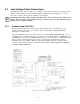
5.6 Low Voltage Input Connections
There are two types of Low Voltage inputs: Analog (e.g., 4-20mA) and Dry Contact. The Low Voltage
Input connection block is labeled J4 'INPUT' (see Figure 6). It contains four-pairs of inputs: Analog
Input, Alarm, Drum and Second Analog Input.
THE DRY CONTACT INPUTS ARE SELF-POWERED. SUPPLY ONLY A MECHANICAL SWITCH
CLOSURE TO ACTIVATE
. DO NOT ATTACH EXTERNALLY POWERED CIRCUITRY.
Figure 6. Low Voltage Input.