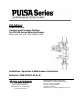
PULSAlarm Leak Detection Vacuum and Pressure Options For PULSA Series Metering Pumps Models 680, 880, 7120, 7440, 7660, and 8480 Installation, Operation & Maintenance Instruction Bulletin #: IOM–PSVLD-03 Rv B Manufacturers of Quality Pumps, Controls and Systems ENGINEERED PUMP OPERATIONS 2883 Brighton Henrietta Townline Road Rochester, New York, 14623 Telephone (585) 292-8000 Fax (585) 424-5619 www.pulsa.com E-mail:pulsa@idexcorp.
Pulsafeeder Factory Service Policy Should you experience a problem with your Pulsafeeder pump, first consult the troubleshooting guide in your operation and maintenance manual. If the problem is not covered or cannot be solved, please contact your local Pulsafeeder Sales Representative, or Technical Services Department for further assistance. Trained technicians are available to diagnose your problem and arrange a solution.
Table of Contents 1. SYSTEM INFORMATION ............................................................................................... 5 1.1 Description and Theory of Operation............................................................... 5 1.2 PULSAlarm Reagent Head.............................................................................. 6 1.3 PULSAlarm Leak Detection Diaphragm .......................................................... 6 1.4 Diaphragm Construction............................
Conventions: . A WARNING DEFINES A CONDITION THAT COULD CAUSE DAMAGE TO BOTH THE EQUIPMENT AND THE PERSONNEL OPERATING IT. PAY CLOSE ATTENTION TO ANY WARNING. Notes are general information meant to make operating the equipment easier.
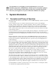
For information on overall pump operation and maintenance, refer to the Installation, Operation, and Maintenance manual specific to the model of pump in question. The information in this bulletin pertains only to the PULSAlarm leak detection system supplied as an option on Pulsafeeder PULSA Series pumps. 1. System Information 1.1 Description and Theory of Operation The PULSAlarm leak detection system utilizes a two-layer PTFE diaphragm, coupled to a pressure or vacuum switch.
1.2 PULSAlarm Reagent Head The PULSAlarm leak detection reagent head assembly consists of reagent head, leak detection diaphragm, suction and discharge check valves, bleed port, and optional switch and gauge.
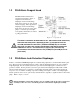
1.4 Diaphragm Construction The adhesive rings aid in assembly and are not present for sealing purposes.
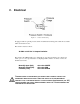
2. Electrical Figure 3 – switch and housing If equipped with an optional pressure switch, install electrical wiring and conduit in accordance with local electrical codes. The switch is rated as follows: 30 VDC or 125 VAC 1 Ampere Resistive. The switch is the SPDT (single pole, double throw) type and can therefore be connected to either open or to close upon detection of diaphragm leak condition.
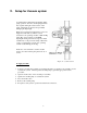
3. Setup for Vacuum system A vacuum must be maintained at all times during pump operation, otherwise, the diaphragm halves may separate during the suction stroke of the pump, reducing flow capacity and potentially damaging the diaphragm. Pumps incorporating the leak detection option are shipped from the factory with the system evacuated to the operating vacuum of 650 mm Hg (26 in. Hg). Due to flexure of the PTFE diaphragms during transit and storage, the initial vacuum may not be present at startup.
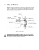
4. Setup for Pressure Pumps incorporating pressure leak detection are shipped from the factory with the system fully set up to work at full pump pressure. No further setup is required. The standard factory barrier fluid is silicone oil, if any other customer-specified media is used it must be compatible with construction materials. The system will require proper setup after maintenance or repairs, see the following page for the proper procedure.
To set up Pressure: 1. Complete re-assembly of the diaphragm, reagent head, and external components if they were taken apart. Ensure that reagent head and tie-bar bolts are tightened according to the appropriate torque specifications 2. Remove the pressure gauge from the housing body and replace it with a straight tubing adaptor fitting. This will be referred to in this document as the “outlet side” fitting Figure 6 – fitting for priming “outlet side” 3.
4. The method used to prime the system will vary with the chosen barrier fluid. The fluid must be introduced under pressure on the inlet side. This pressure can be normal water pressure if water is being used. It can be provided by a pressurized tank and/or a hand pump. Refer to Section 4.1 for instructions on how to utilize a pressure chamber to achieve the fill. The fill pressure should not exceed 30 psi (2 bar) 5.
14. In order to fully balance and evacuate the leak detection system, the pump must now run at normal discharge pressure for a period of about 30 minutes to one hour. This ensures that excess barrier fluid is fully evacuated from the system. 15. Supply either process fluid, or test fluid (i.e. water) to the suction fitting and ensure that the discharge system is configured for safe operation.
4.1 Pressure fill chamber Under certain conditions, when barrier fluids other than water are used, a pressure chamber can be fabricated from readily available fittings that allows the barrier fluid to be fed under pressure to the inlet of the system. Users may wish to fabricate a device based upon this sketch which will aid in the setup of the pressure-based system.
1. Connect a vacuum pump to the top fitting of the fluid fill device. Open BOTH valves on the device. 2. Place the lower fill tube into the container of the barrier fluid 3. Using the vacuum function, use the hand pump to draw several ounces of fluid up into the fill device. 4. Close both valves on the fill device 5. Remove the hose and fitting from the container, and connect the fluid fill device to the inlet fitting on the pump head (the fitting with the needle valve). 6.
5. Maintenance Although the PULSAlarm leak detection system requires minimal maintenance, vacuum must be maintained to prevent false alarms and diaphragm damage. 5.1 Switch Setpoint Adjustment If the optional switch is purchased, it is factory preset at the specified vacuum setpoint, 150 mm Hg (6 in. Hg), at which loss of vacuum causes the vacuum switch to actuate. The standard pressure switch is set to actuate at 5 psig. Use the following procedure to perform a Vacuum setpoint adjustment: 1.
5.2 PULSAlarm Diaphragm Maintenance After diaphragm failure, pressurized process fluid can be present in any part of the PULSAlarm leak detection vacuum system. Take appropriate precautions and handle with care. Figure 10 – diaphragm and head orientation 5.2.1 PULSAlarm Diaphragm Removal Use the following procedure to remove the Leak Detection Diaphragm: 1. 2. 3. 4. 5. 6. 7. 8. 9. 10. 11. Disconnect the power source to the drive motor.
5.2.2 Inspection Remove and inspect the diaphragm assembly. It may have taken a permanent convex/concave set as a result of normal flexure and conformance to the dish-plate. This condition is normal and is not cause for replacement. The diaphragm must be replaced if it is deformed, dimpled, or obviously damaged. If the diaphragms have been removed from the spacer ring, the entire assembly should be replaced to ensure proper sealing of its components. 5.2.3 PULSAlarm Diaphragm Reinstallation 1.
5.3 Leak Detection system conversion Leak detection system conversion information can be found in Bulletin CV-LD-0203 (vacuum to pressure system). For further conversion information and kits, please contact your local Pulsafeeder sales representative. 6. Silicone Fluid MSDS The following safety information is provided for the silicone fluid used as standard in the PULSAlarm pressure-based leak detection system.
Medical Conditions Aggravated by Exposure No known applicable information. The above listed potential effects of overexposure are based on actual data, results of studies performed upon similar compositions, component data and/or expert review of the product. Please refer to Section 11 for the detailed toxicology information. 4. FIRST AID MEASURES Eye: Immediately flush with water. Skin: No first aid should be needed. Inhalation: No first aid should be needed. Oral: No first aid should be needed.
Component Exposure Limits There are no components with workplace exposure limits. Engineering Controls Local Ventilation: None should be needed. General Ventilation: Recommended. Personal Protective Equipment for Routine Handling Eyes: Use proper protection - safety glasses as a minimum. Skin: Washing at mealtime and end of shift is adequate. Suitable Gloves: No special protection needed. Inhalation: No respiratory protection should be needed. Suitable Respirator: None should be needed.
unless generated as an aerosol. Water: This product has a very low water solubility (< 100 ppb). As it has a specific gravity of < 1, if discharged to water, it will initially form a surface film. As the product is non volatile and has a high binding affinity for particulate matter, it will adsorb to particulates and sediment out. Soil: If discharged to surface water, this product will bind to sediment.
Section 304 CERCLA Hazardous Substances: None. Section 312 Hazard Class: Acute: No Chronic: No Fire: No Pressure: No Reactive: No Section 313 Toxic Chemicals: None present or none present in regulated quantities. Supplemental State Compliance Information California Warning: This product contains the following chemical(s) listed by the State of California under the Safe Drinking Water and Toxic Enforcement Act of 1986 (Proposition 65) as being known to cause cancer, birth defects or other reproductive harm.
IOM–PSVLD-03 Rev B Engineered Pump Operations 2 8 8 3 B r i g h t o n - H e n r i e t t a To w n l i n e R o a d Rochester, NY 14623 Te l e p h o n e ( 5 8 5 ) 2 9 2 - 8 0 0 0 F a x ( 5 8 5 ) 4 2 4 - 5 6 1 9 http://www.pulsa.com pulsa@idexcorp.