INSTALLATION OPERATION MAINTENANCE INSTRUCTION BULLETIN No.
PULSA SERIES GUARANTEE Should you experience a problem with your Pulsafeeder pump, first consult the troubleshooting guide in your operation and maintenance manual. If the problem is not covered or cannot be solved, please contact your local Pulsafeeder Sales Representative, or our Technical Services Department for further assistance. Trained technicians are available to diagnose your problem and arrange a solution.
Table of Contents 1. INTRODUCTION ........................................................................................................................................ 1 1.1 General Description ................................................................................................................ 1 1.2 Options ..................................................................................................................................... 3 Input Signals ......................................
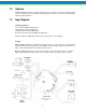
1. Introduction 1.1 General Description The PULSAmatic actuator converts reciprocating motion of the pump into rotary motion to turn the pump’s stroke adjustment screw. By selectively engaging either of the two oppositely oriented, one-way clutches, one of two corresponding nuts hat ordinarily rotate freely on a “diamond” actuator shaft is blocked form rotation when the shaft moves longitudinally in one direction.
2
1.2 Options The PULSAmatic actuator is configured at the factory for a variety of options, both singly and in various combinations. The appropriate wiring diagrams external to the circuit board are included with each pump shipment. 1.3 Input Signals . Standard signals are: 1-5 mA DC @ 2000 ohm Impedance 4-20 mA DC @ 470 ohm Impedance 10-50 mA DC @ 180 ohm Impedance 0-10 V DC @ Greater than 270,000 ohm Impedance Slide wire (Remote, 1000-ohm manual control potentiometer, user-supplied).
1.4 Control Modes Ratio Control- When ratio control is applied, the range of stroke adjustment is proportionally reduced to a level equal to the ratio setting. For example, at a ratio setting of 60%, the full span of the input signal commands the pump to operate between zero and 60% of full stroke rather than over the full range of the stroke. The ratio is manually set between zero and 100% using a remote potentiometer.
2. Equipment Inspection 1. Check all equipment for completeness against the order and for shipping damage. Shortages or damage should be reported immediately to your PULSA Series representative. 2. Check pump and PULSAmatic stroke control identification tags for serial and model numbers. There are two tags: one on the pump gearbox which includes the pump model number and another on the PULSAmatic enclosure.
4. INSTALLATION 4.1 Wiring Up (Refer to any special wiring diagrams and installation drawings supplied by Pulsafeeder). AC power lines should be routed to the actuator via a separate conduit from the control signal and any optional accessory wiring. A separate switched and protected circuit is recommended for the actuator power supply. Remove the PULSAmatic actuator cover, which is secured by two screws, or screwed on, in the case of an explosion proof enclosure.
Operation of the second limit switch (the one closest to the circuit board) may be checked in a similar manner. The limit switch should be open at a stroke indicator reading between 001 and 000. If either of the limit switches appears to be out of adjustment refer to “repairs- Limit Switch Adjustment”. Barring any problems proceed with “Calibrations and Adjustments”. Refer also to the “Equipment Startup” section of the pump Installation, Operation, and Maintenance Instructions. 5.
Without Ratio Control – Coarse Adjustment 1. Place the override switch in the “out” or manual position. The pump need not be running for coarse adjustment. 2. Set up a voltmeter to read a full scale DC voltage of 10. 3. Connect the positive lead of the voltmeter to TB2-2 and the negative lead to TB2-1. 4. Set the control signal at the low end (0%) and record the voltage. 5. Set the control signal at the high end (100%) and record the voltage. 6.
6. Adjust the “Ratio Zero” potentiometer on the circuit board (to the right of TB3) to +/- 0.0 volts. 7. With the voltmeter remaining as set up in step (5) above, set the control signal at the high end (100%) and record the voltage. 8. Set up a voltmeter for CD voltage measurement between TB2-5 (positive) and TB2-1 (common). 9. Adjust the “LO” trim potentiometer on the circuit board to +/-0.0 volts. 10. Set up a voltmeter for DC voltage measurement between TB2-4 (positive) and TB2-1 (common). 11.
5.4 Auto-Manual Calibration This procedure trims the manual control potentiometer to the low and high ends o the actual input control signal. The main circuit board must be calibrated prior to this procedure. For current type control signals, a resistor is installed across terminals of the auto-manual switch. If present, this resistor must remain in place.
6. Repairs 6.1 Limit Switch Adjustment This procedure adjust the limit switches to prevent the pump mechanism from jamming due to over travel, without significantly restricting the range of stroke length settings. The limit switches disable the actuator from operating below zero strokes or above full stroke, either of which can cause jamming. For this reason, correct limit switch adjustment is very important. The procedure for checking limit switch adjustment is given under “Installation- Start Up”.
6.3 Zero Alignment The actuator mechanism must be aligned relative to the pump drive in order to permit the full range of stroke adjustment. Preliminary Check 1. Set up a multimeter for resistance measurement across the limit switch (in subassembly #635, Figure 6 or 7) closest to the circuit board. 2. Turn the handwheel clockwise to decrease pump stroke length until the meter indicates an open switch. Record the mechanical stroke indicator reading at this point.
4. Remove the cotter pin, Item #539, nut, Item # 535, and washer, Item #534 from the end of the diamond screw shaft on top of the housing. 5. Remove the screws to the rear gearbox cover, Item #526A. 6. Lift the cover slightly and pull it back towards the motor. As the shaft disengages, the miter gear, Item #533, bushing, Item #532, and bushing pin, Item #538, will come loose. Don’t allow them to fall into the gear box. 7.
6.5 Jammed Slider Block 1. The slider block is probably jammed if the stroke cannot be freely adjusted using the handwheel with the override switch pulled out and no pressure load on the pump. To confirm the problem, remove the cover (Item #529A, Figures 8 and 9) over the oscillating housing and observe the position of the front connecting rod, Item #353, where it enters the housing, Item #351 where Figure 5 refers.
Models 7660 and 8480 Remove the housing pin flange bolts and thread them into the tapped holes in the flange. Tighten all bolts equally to remove the pins. 7. Pull the housing assembly (#540) rearward until the cross head wrist pin (#550) is exposed. Loosen the set screw (#549) located on the rear of the crosshead (#551), and slide the wrist pin out. Complete removal of the housing assembly is now possible. 8.
9. Troubleshooting PROBLEM PROBABLE CAUSE 1. 2. 3. 4. 5. Actuator Does Not Adjust Actuator Adjusts to Incorrect Setting Actuator Adjusts in One Direction Only Brake Slipping Erratic Operation No AC power to actuator. Pump not running. Override switch not pushed in. Control signal off, incorrect, or of inverted polarity. Ratio control (if so equipped) set at or very near zero percent. 6. Blown fuse (see Figure 4 for location). 7. Wiring discontinuity. 8. Brake slipping (see “Troubleshooting”). 9.
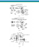
Figure 5 17 AP00229
MODEL 7120/7440 AE HOUSING ASSEMBLY PULSAMATIC CONTROL (Reference Figure 5) ITEM PART NAME QUANTITY 351 Housing 1 352 Housing Block 1 353 Connecting Rod-Front 1 354 Pin 1 355 Pin 1 356 Adjustment Screw 1 357 Miter Gear 1 358 Housing Cap Assembly 1 359 Cap Screw 3 360 Washer 3 361 Washer 1 362 Nut 2 300 Housing Assembly: Consists of all the above components pre-assembled 1 18
MODEL 7660/8480 AE HOUSING ASSEMBLY PULSAMATIC CONTROL (Reference Figure 5) ITEM PART NAME QUANTITY 351 Housing 1 352 Housing Block 1 353 Connecting Rod-Front 1 354 Pin 1 355 Pin 1 356 Adjustment Screw 1 357 Miter Gear 1 358 Housing Cap Assembly 1 359 Cap Screw 4 360 Washer 4 361 Washer 1 362 Nut 2 300 Housing Assembly: Consists of all the above components pre-assembled 1 19
Figure 6 Standard NEMA 4 ENCLOSURE 20
MODEL 7120/7440/7660/8480 NEMA 4 ACTUATOR ASSEMBLY PULSAMATIC CONTROL (Reference Figure 6) 21 AP00332
AP00333 Figure 7 EXPLOSION PROOF ENCLOSURE MODEL 7120/7440/7660/8480 AP00334 22
NEMA 7 ACTUATOR ASSEMBLY PULSAMATIC CONTROL (Reference Figure 7) 23 AP00335
Figure 8 MODELS 7120 AND 7440 MODEL 7120/7440 -AE 24 AP00330
CONTROL ASSEMBLY PULSAMATIC CONTROL (Reference Figure 8) ITEM PART NAME QUANTITY 501 Handwheel 1 502 Set Screw 1 503 Counter 1 504 Round Head Screw 2 505 Counter Gasket 1 506 Bushing 1 507 Set Screw 1 508 Mounting Plate 1 509 Cap Screw 4 510 Gasket 5 511 Gear 48T 1 512 Gear 16T 1 513 Set Screw 1 514 Gear 22T 1 515 Spacer 1 516 Washer 1 517 Washer 1 518 Cap Screw 1 519 Insert 1 520 Miter Gear 1 521 Set Screw 1 522 Spring 1 523 o-Ring 1
529A Breather Cover 1 529B Diaphragm 1 530 Fillister Head Screw 6 531 Drive Shaft Assembly 1 532 Bushing 1 533 Miter Gear 1 534 Washer 1 535 Slotted Nut 1 536 Actuator Assembly 1 537 Spacer 1 538 Pin 1 539 Cotter Pin 1 540 Housing Assembly 1 541 Warning Plate 1 542 Drive Screw 4 543 Cap Screw 4 544 Pin 1 545 Cotter Pin 1 546 Set Screw 2 547 Housing Bolt 2 548 o-Ring 2 549 Set Screw 1 550 Pin 1 551 Crosshead 1 552 Fillister Head Screw
Figure 9 MODELS 7660 AND 8480 27 AP00331
MODEL 7660/8480 -AE CONTROL ASSEMBLY PULSAMATIC CONTROL (Reference Figure 9) ITEM PART NAME QUANTITY 501 Handwheel 1 502 Set Screw 1 503 Counter 1 504 Round Head Screw 2 505 Counter Gasket 1 506 Bushing 1 507 Set Screw 1 508 Mounting Plate 1 509 Cap Screw 4 510 Gasket 5 511 Gear 48T 1 512 Gear 16T 1 513 Set Screw 1 514 Gear 22T 1 515 Spacer 1 516 Washer 1 517 Washer 1 18 Cap Screw 1 519 Insert 1 520 Miter Gear 1 521 Set Screw 1 522 Spring
526A Cover 1 526B Cover Gasket 1 527 Dip Stick Assembly 1 528A Front Cover 1 528B Diaphragm 1 529A Cover Plate 1 529B Gasket 1 530 Fillister Head Screw 10 531 Drive Shaft Assembly 1 532 Bushing 1 533 Miter Gear 1 534 Washer 1 535 Slotted Nut 1 536 Actuator Assembly 1 537 Spacer 1 538 Pin 1 539 Cotter Pin 1 540 Housing Assembly 1 541 Warning Plate 1 542 Drive Screw 4 543 Cap Screw 4 544 Pin 1 545 Cotter Pin 1 546 Hex Head Bolt 3 547 Hou
30 This page is intentionally left blank.
31 PSM418 H11