
User guide

2. Field Wiring
The Cruise Control
™
is designed to simplify installation for both single and multiple drive enclosures. In all
cases, field terminals are color-coded and separated from terminals used for internal wiring. The following notes
apply:
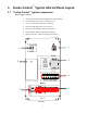
2.1 Terminal Block
A standard terminal block layout is used regardless of which options are specified, making the layout of Terminal
Block 1 (TB1) identical for all configurations. Although terminal blocks for all options are present, only terminal
blocks associated with the specified and included options are incorporated into the circuit. This simplifies
assembly and provides a consistent interface. The terminal blocks are color-coded to further simplify wiring
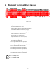
2.1.1 Terminal Block Color Codes
Black Motor Power Connection (Armature and Field)
Red External Fault Detection Options (Hi Temp, etc.)
Green Drive Status (Drive Running, In Remote Mode, etc.)
Yellow Drive Start Input
Blue Analog or Low Voltage I/O (Drive speed reference, Chemalarm
™
Probe, etc.)
Orange Tachometer feedback connection
2.2 Documentation
Standard documentation practices were followed to simplify cross referencing between the system drawings and
the terminal block wiring numbers. The first three digits of the four digit number represent the page and line
numbers where the wire appears. The last digit represents the order of occurrence on a given line number. For
example, wire 1281 is the first wire located on line 28 on page #1.
2