
User guide

9. Digital Panel Meters
The Speed and Stroke Length Meters are configured and programmed for your application during
assembly. The following information is for reference only.
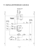
9.1 Jumper Programming
The input and output modules are designed to cover several ranges. For proper operation, the jumpers should be
set as follows:
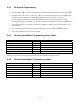
Percent Speed Meter Jumper Programming
Description Desired Range Slot Number Position
DC Voltage Input Module (5100530) 0-200 Volts 1 6-3
Optional DC Analog Output Module (5100560) 4-20mA 5 Up, Down, Up
Percent Stroke Meter Jumper Programming
Description Slot Number Position
DC Current Input Module (5100532) 1 5-6
Optional DC Analog Output Module (5100560) 5 Up, Down, Up
9.2 Meter Functional Programming
For proper operation, the speed meter must be configured for operation at the input range selected by jumpers
above and programmed for the specific application.
9.2.1 Input Range Selection
1. Press and hold the S and ▲ keys simultaneously and switch on the unit. The display shows PAS. The
display will show
0 two seconds after the keys are released.
2. Press the ▲ key until
66 is displayed.
3. Press the
S key and the display will show SEL.
4. Press the
S key to enter range selection mode. The display will show the current range code (a number
between 0 and 12).
5. Use the ▲ or ▼ keys to select the range code shown in the table.
6. Press S to accept the new range code and return to RUN mode.
13