DC Variable Speed Drive Panel Installation, Operation & Maintenance Instruction Manual Bulletin #: CC-IOM-0103-D Manufacturers of Quality Pumps, Controls and Systems ENGINEERED PUMP OPERATIONS 2883 Brighton Henrietta Townline Road Rochester, New York, 14623 Telephone (585) 292-8000 Fax (585) 424-5619 www.pulsa.com pulsa@idexcorp.
Pulsafeeder Factory Service Policy Should you experience a problem with your Cruise Control™ variable speed control panel, first consult the troubleshooting guide in your operation and maintenance manual. If the problem is not covered or cannot be solved, please contact your local Pulsafeeder Sales Representative, or our Technical Services Department for further assistance. Trained technicians are available to diagnose your problem and arrange a solution.
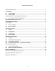
Table of Contents 1. SINGLE PAGE START-UP ...................................................................................................................... 1 2. FIELD WIRING ...................................................................................................................................... 2 2.1 Terminal Block ........................................................................................................................ 2 2.2 Documentation .................................
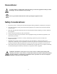
Conventions: A warning defines a condition that could cause damage to both the equipment and the personnel operating it. Pay close attention to any warning. Notes are general information meant to make operating the equipment easier. Safety Considerations: 1. Disconnect power to control panel and related equipment during installation, maintenance, and repairs. 2. Wire and ground this control panel and all related equipment in accordance with all local and national electrical codes. 3.
1. Single Page Start-Up Although the Cruise Control™ is factory set to your specifications, it is always good practice to verify jumper settings to insure nothing was removed, changed, or damaged during shipping or installation. Once a visual inspection is complete, connections can be made. Refer to Section 4 for terminal block layout. Ensure that all electrical wiring meets applicable local and national electrical codes as well as appropriate facility standards. Motor and Control Connections 1.
2. Field Wiring The Cruise Control™ is designed to simplify installation for both single and multiple drive enclosures. In all cases, field terminals are color-coded and separated from terminals used for internal wiring. The following notes apply: 2.1 Terminal Block A standard terminal block layout is used regardless of which options are specified, making the layout of Terminal Block 1 (TB1) identical for all configurations.
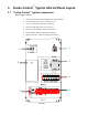
3. Cruise Control™ Typical Internal Panel Layout 3.1 Cruise Control™ typical components Refer to Figure 1, below 1. Non-fused disconnect and incoming power terminal blocks. 2. Circuit breakers (main, drive, components, etc.) 3. Control or Isolation Transformer (if needed) 4. Control system relays (drive start, fault, etc.) 5. DC Drive (with armature contactor if needed) 6. Terminal block (internal and field terminations) 7.
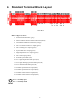
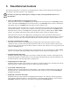
4. Standard Terminal Block Layout 4 8 9 6 7 2 1 3 FIGURE 2 Refer to figure 2, above: 1. Internal terminal blocks (gray) 2. Motor armature & motor field connections (black) 3. Tachometer feedback connections (orange) 4. Drive in remote mode N.O. output (green) 5. Drive running N.O. output (green) 6. System fault N.O. output (green) 7. High temperature N.O. output (green) 8. Drive start input (yellow) 9. External system fault (red) 10. N.C. high temperature fault input (red) 11. N.O.
5. Panel External Controls The following information is for reference on intended operation. Please consult with the Project Engineer for any changes or procedures specific to your installation. Note that your panel may contain options or changes to satisfy certain specifications that are not described here. • Motor Start Hand/Off/Auto Position Selector Switch: When this selector switch is in the Hand position, the pump motor will start based on the Start/Stop selector switch.
• Motor High Temp Fault Amber Pilot Light Illuminates when the motor experiences a thermal overload or high temperature condition. This will also cause the appropriate relay to latch, and the pump will stop. This light will not go off until the fault condition is removed and the Fault Reset pushbutton is depressed. This fault will also signal the System Fault light. • High Discharge Pressure Amber Pilot Light Illuminates when the system experiences a high discharge pressure condition.
6. Field Wiring Do not touch any of the components or wires located in the panel without first removing power to this panel. Any of these wires may have voltage connected to them. 6.1 Power and Motor Main power into this system is supplied in the upper right corner inside the panel. This system is powered with 120 or 220 volt AC power, single phase. All power lines are terminated at the disconnect or terminal block located in the upper right-most corner of the enclosure.
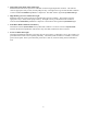
• System fault output The System Fault output will be a normally open contact signal to the main panel. The common signal will connect to terminal 1341, and active signal will connect at terminal 1342. These wires should not exceed 14 AWG wires. • Local/Remote status output The System in Remote output will be a normally open contact signal to the main panel. This contact will close when the Cruise Control is ready to accept a run signal from the main panel.
7. Drive Specifications The Cruise Control™ comes standard with a Control Techniques Focus 3™ DC Drive. The panel documentation includes the complete User Manual from Control Techniques. Included below are general specifications for this DC drive and control panel system. These specifications are applicable only to the Focus 3™ drive, if your panel has been specified with an alternate DC SCR drive, please refer to the appropriate manufacturer’s literature supplied with your panel system. 7.
8. DC Drive Configuration The Control Techniques DC Drive is properly configured for your application during assembly. The following information is for reference only. Some panels may be supplied with an alternate drive to conform to the user’s specification. If your panel is so equipped, please refer to the appropriate manufacturer’s literature for this information. 8.
8.3 Drive Speed Calibration See drive layout, Figure 3, on following page. Requirements and Warnings: • • • • • Pump will operate during testing System must be open to allow flow, or pump must be disconnected from system Must be safe to operate pump Field wiring should be verified Applicable safety precautions should be followed Use the following sequence to calibrate the drive. It is assumed that maximum speed will be either 90V or 180V as applicable.
8.4 Control Technique Focus 3™ F3N2C Control Board Jumper and Potentiometer Positions DECEL ACCEL JP9 OFFSET SPEED MIN SPEED MAX SPEED IR COMP ZERO BIAS CURRENT REF. GAIN JP4 JP3 JP8 SPEED REF.
9. Digital Panel Meters The Speed and Stroke Length Meters are configured and programmed for your application during assembly. The following information is for reference only. 9.1 Jumper Programming The input and output modules are designed to cover several ranges.
9.2.2 Functional Programming 1. Press and hold the S key; then press the ▼ key. Release both immediately when display shows PAS. 2. If the password is not 0 (zero), use the ▲ or ▼ keys to select the proper password. Press S to enter and move to the next parameter. All meters are shipped with the password set to 0 (zero). 3. At each parameter, the display will show the parameters for two seconds, then display the value associated with the given parameter.
10. Elapsed Time Meters The Elapsed Time Meters are configured and programmed for your application during assembly. The following information is for reference only: • Elapsed Timer Setup The setup switches for this elapsed timer are located at the bottom of the meter inside the enclosure. Switch number 1 is located on the side under the reset button, and switch number 2 is located on the other side. • Time-range Switch (2) Set this switch towards the terminal block (back of device) for 0.
11.
12.
13. Additional Information See the spreadsheet and drawing package included with your Cruise Control for complete panel bill of materials and wiring information.
19
Engineered Pump Operations 2 8 8 3 B r i g h t o n - H e n r i e t t a T o wn l i n e R o a d Rochester, NY 14623 Telephone (585) 292-8000 Fax (585) 424-5619 pulsa@idexcorp.com h t t p : / / w w w. p u l s a .