Installation, Operation and Maintenance Manual Pre-Engineered Skid Systems Manufacturers of Quality Pumps, Controls, and Systems Bulletin PES00039, Rev. B Standard Product Operations 27101 Airport Rd., Punta Gorda, FL 33982 Tel: (941) 575-3800 Tel: (800) 333-6677 Fax: (941) 575-4085 Fax: (800) 456-4085 spotech@pulsa.com www.Pulsafeeder.
Pre-Engineered Skid Systems Installation, Operation and Maintenance Manual Pulsafeeder Factory Service Policy Should you experience a problem with your Pre-Engineered Skid System, first consult the troubleshooting guide in this operation and maintenance manual, as well as the information in the manual for your Pulsatron pump.
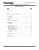
Pre-Engineered Skid Systems Installation, Operation and Maintenance Manual Table of Contents Topic Page Introduction........................................................................................................... 4 Safety .................................................................................................................... 5 Skid Layout and Component Descriptions ........................................................... 6 Systems Overview .......................................
Pre-Engineered Skid Systems Installation, Operation and Maintenance Manual Introduction Congratulations! With the Pulsafeeder Pre-Engineered Skid System, you have the finest chemical dosing equipment platform available. This system includes the essential elements for successful installation and operation of your dosing pump(s). You are encouraged to: READ THIS MANUAL! Pulsafeeder Pre-Engineered Skid Systems are designed to support single and dual pump installations.
Pre-Engineered Skid Systems Installation, Operation and Maintenance Manual Safety Your safety is of the utmost concern to Pulsafeeder. Dosing pumps and systems can handle harsh or toxic chemicals and exposure can lead to serious injury or death. Always wear appropriate protective clothing (for example, safety glasses, gloves, coveralls, etc.) and follow safe handling procedures. Pay attention to what you’re doing and note safety advisories where they are shown throughout this manual.
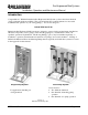
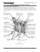
Pre-Engineered Skid Systems Installation, Operation and Maintenance Manual Skid Layout and Components Figure 2, below, illustrates a dual pump skid system (Pulsafeeder Designation “2A”) for flooded suction (chemical source above the pump centerline) as shown on Page 7. This system can be used for two different chemicals or for redundant pump operation with one chemical. Your skid system may be less complex than this. Note the various components and their descriptions as they apply to your skid system.
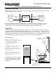
Pre-Engineered Skid Systems Installation, Operation and Maintenance Manual Systems Overview The Pulsafeeder Pre-Engineered Skid System is designed to pump chemicals at precisely controlled rates into another process or system. Dosing Chemical Supply Side Process Side Pulsafeeder Skid System Served Process or System Proper arrangement of piping and appurtenances on both the supply side and the process side are critical to the successful operation of the overall system.
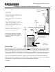
Pre-Engineered Skid Systems Installation, Operation and Maintenance Manual Supply Side, Continued Skid Outlet Connection Suction Lift Pressure Relief Valve This is the most common arrangement for chemical metering applications since there is less chance of spillage. Note that the maximum recommended lift is 5 feet (1.5m). Skid Suction Connection Since the Supply Line will be in a vacuum condition, attention should be paid to the vapor pressure of the pumped liquid.
Pre-Engineered Skid Systems Installation, Operation and Maintenance Manual Process Side, Continued… Note comments on Process Side Piping/Tubing on the illustration, below: Pressure Dissipation, Drain, Vent, Flush Provision It is strongly recommended that this type of provision be added to the process side of the injection system to facilitate maintenance. When system pressure is dissipated or when venting, spray may occur which could cause serious harm or injury.
Pre-Engineered Skid Systems Installation, Operation and Maintenance Manual Installation Prior to attempting installation, familiarize yourself with the layout and components furnished with your Pulsafeeder Pre-Engineered Skid System. These vary from system to system – review the documentation supplied with your order. Inspect your skid system for damage which may have occurred during transit.
Pre-Engineered Skid Systems Installation, Operation and Maintenance Manual Installation, Continued… Owner-Installed Piping/Tubing The next series of steps are the connection of your piping/tubing which include the chemical supply line, discharge line, pressure relief/bypass line and an air bleed return line.
Pre-Engineered Skid Systems Installation, Operation and Maintenance Manual Installation, Continued… Owner-Installed Piping/Tubing, Continued… Air Bleed Valve Bypass Line Discharge Tubing Air Bleed Bypass Line Air Bleed Valve Air Valve Opening Knob Pump Body Pump Discharge Pump Suction Suction Tubing Figure 9 Air Bleed Valve Configuration Although most metering pumps are self-priming, they can not pump against pressure when handling air in the priming cycle.
Pre-Engineered Skid Systems Installation, Operation and Maintenance Manual Initial Prime The pump must be primed before it can function within the system. This will require an initial start of the pump. ! CAUTION Thoroughly review the installation, operation and maintenance manual for your pump prior to starting. Follow pump startup instructions. Failure to do so may result in damage to equipment or serious injury. Flooded Suction System 1. Close Skid Discharge Valve and Column Isolation Valve 2.
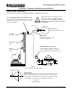
Pre-Engineered Skid Systems Installation, Operation and Maintenance Manual Initial Prime, Continued… System with Suction Lift Discharge Line to Process Skid Discharge Connection/Valve Air Bleed Bypass Line Air Bleed Valve Calibration Column Pump Column Isolation Valve Suction Line Skid Suction Connection/Valve Chemical Source With a suction lift configuration, the entire suction arrangement (suction line and Skid suction piping) as well as the pump must be purged of air before the pump can function
Pre-Engineered Skid Systems Installation, Operation and Maintenance Manual Setting Valves and Pulsation Dampener If furnished with your Pulsafeeder Pre-Engineered Skid System, the Pressure Relief Valve, Back Pressure Valve and Pulsation Dampener will be pre-set at the factory in accordance with Table 1 located in the Appendix of this manual. These pressure settings are related to the piping and components furnished with your skid as well as the pump(s) if furnished with the skid.
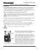
Pre-Engineered Skid Systems Installation, Operation and Maintenance Manual Pulsation Dampener Positive displacement pumps will create pressure pulsations in the discharge line which can be damaging to piping or system components. A pulsation dampener utilizes an air chamber separated from the pumped liquid by a diaphragm to cushion any pulsation(s) and provide a steady flow. The air pressure in the Pulsation Dampener is generally set at 80% of the system operating pressure.
Pre-Engineered Skid Systems Installation, Operation and Maintenance Manual Set Pressure Relief Valve (PRV) Refer to Table 1 in the Appendix, Page 23, for recommended PRV pressure settings. With Pressure Relief Valve and Back Pressure Valve fully open (lowest pressure setting), 1. Close Skid Discharge Valve. 2. Start pump, monitor Skid Discharge Gauge pressure. It should pulse slightly. On most Pulsafeeder Pre-Engineered Skid systems, relief flow should be passing through the PRV into the suction header.
Pre-Engineered Skid Systems Installation, Operation and Maintenance Manual Flow Calibration Chemical metering systems are designed to provide chemicals to a process at precise flow rates. Metering pump output (flow rate) can be set as a function of both stroke length and stroke frequency. A Calibration Column is used to determine pump flow rate and to enable flow rate adjustments. The column must be filled with the dosing chemical prior to performing the calibration.
Pre-Engineered Skid Systems Installation, Operation and Maintenance Manual Filling Calibration Column, Continued… Filling the Calibration Column on a skid without a cross-connect will likely require filling through the top of the Calibration Column. ! Calibration Column Use extreme care when handling chemicals. Avoid any spray, splatter or spilling. Always wear appropriate protective clothing.
Pre-Engineered Skid Systems Installation, Operation and Maintenance Manual Flow Calibration Procedure The Calibration Column is filled to slightly above the top mark of the scale. The pump is then run in the system while being fed from the Calibration Column. After a 30 second time period, the liquid level reading on the scale will be a direct readout of the pump flow rate in US Gallons/hr. (Note that a milliliter scale is also shown on the Calibration Column) With the pump running in the system 1.
Pre-Engineered Skid Systems Installation, Operation and Maintenance Manual Routine Maintenance Before performing any maintenance on your skid system or pump, ! WARNING Skid components, pump(s) and your process piping may be under pressure! Prior to working on any portion of the Skid System, disconnect pump(s) from power supply, de-pressurize the entire system and drain chemicals from the lines. Flush and neutralize as necessary. Always wear suitable protection (gloves, safety glasses/goggles, etc.
Pre-Engineered Skid Systems Installation, Operation and Maintenance Manual Troubleshooting Guide Problem Possible Cause Remedy Air entering suction line Check fittings for tightness Check integrity of tubing Check level in suction source – must be above foot valve at inlet Re-configure suction line to eliminate air pocket(s) Inspect, replace tubing Refill, re-prime pump Re-prime pump Reduce suction lift or change to flooded suction Consider chemical storage temperature Check strainer, clean Check Press
Pre-Engineered Skid Systems Installation, Operation and Maintenance Manual Table 1 – Factory Pre-sets for Components Pump, if furnished with Skid, and System Description Pump Data System Calibration Size GPD PSI Configuration Column Size K2 3 300 12 5 B2 5 2 6 C2 6 C3 10 250 33 12 D3 12 F4 20 H4 41 A2 6 13 12 B3 12 34 22 150 D4 22 G4 42 Standard 200 mL K5 60 H5 76 3 12 A3 12 K3 14 4 24 14 24 100 B4 24 64 30 44 44 E4 44 G5 96 110 H6 120 100 54 30 80 C4 48 50 J7 240 80 K7 192 50 HF 1000 mL (High Flow) H7 240