
Instruction Manual

12
2.2 Electrical Wiring
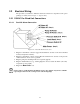
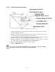
The procedure you will use to make the electrical connections is dependent on the option
package you select (refer to Figure 2 – Options List).
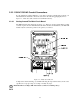
2.2.1 115VAC Pre-Wired Unit Connections
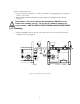
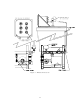
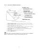
2.2.1.1 Dual AC Alarm Connection
Figure 10 – Dual AC Alarm Connection
1. Plug the 2-wire Molex connector tagged Level Wand into its mate on the end of the PVC
wand (low liquid level switch).
2. Plug the 2-wire Molex connector tagged Pressure Switch #1 into its mate on the pressure
switch attached to the closed loop system.
3. Plug the pump into the Pump #1 Power receptacle (pigtail).
4. Plug the Alarm Indicators (e.g.: warning light) into the associated AC Alarm (#1 & #2)
receptacles (power pigtail).
5. Plug in the Main Power cord.
For the purpose of this manual, the DGF1 is used as the example. If you have a DGF2
repeat steps 2 and 3 for the second pressure switch and pump.