DIGITAL GLYCOL FEEDER DGF1, DGF2 OPERATING INSTRUCTIONS P/N: 72-900-24 Rev J (06-22-07) Manufactures of Quality Pumps, Controls and Systems STANDARD PUMP OPERATION 27101 Airport Road Punta Gorda, FL 33982 Telephone (941) 575-3800 Fax: (941) 575-4085 (800) 333-6677 www.pulsa.
FACTORY SERVICE POLICY Your Digital Glycol Feeder (DGF) is designed to make-up lost glycol in a closed loop system. If you are experiencing a problem with your DGF consult the trouble-shooting guide. If the problem is not covered or cannot be solved, please contact your local Pulsafeeder Representative or our Technical Service Department at (800) 333-6677 for further assistance. Trained individuals are available to diagnose your problem and arrange a solution.
Copyright Copyright ©1999 Pulsafeeder, Inc. All rights reserved. Information in this document is subject to change without notice. No part of this publication may be reproduced, stored in a retrieval system or transmitted in any form or any means electronic or mechanical, including photocopying and recording for any purpose other than the purchaser’s personal use without the written permission of Pulsafeeder, Inc.
Table of Contents 1. INTRODUCTION .....................................................................................................................................1 1.1 Systems and Options..............................................................................................................2 2. INSTALLATION ......................................................................................................................................3 2.1 Assembly............................................
Conventions For the remainder of this bulletin, the following Conventions are in effect. A WARNING DEFINES A CONDITION THAT COULD CAUSE DAMAGE TO BOTH THE EQUIPMENT AND THE PERSONNEL OPERATING IT. PAY CLOSE ATTENTION TO ANY WARNING. Notes are general information meant to make operating the equipment easier. Tips have been included within this bulletin to help the operator run the equipment in the most efficient manner possible.
1. Introduction The Digital Glycol Feeder (DGF), is designed to make-up for lost glycol in a closed loop system. It accomplishes this by monitoring system pressure. When system pressure drops below a set pressure (indicating glycol loss), the pump activates and restores the lost glycol, bringing the system pressure back to the proper operating level.
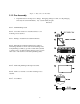
1.1 Systems and Options The Glycol Feeder for Closed Loop Systems includes: • • control unit in a NEMA type 4X enclosure 55 gallon polyethylene tank and stand Refer to Figure 2 – Options List, for Glycol Feeder options.
2. Installation 2.1 Assembly If your DGF is shipped to you unassembled, perform the following: (If you ordered the assembled version go to section 2.2 – Electrical Wiring.) FAILURE TO FOLLOW THESE WARNINGS AND ASSEMBLY INSTRUCTIONS COULD RESULT IN SERIOUS INJURY OR DEATH! • • • • • • • • • • Read all instructions carefully before assembly. Check all connections to ensure they are tight before applying pressure to the system. Wire in accordance to applicable electrical codes.
4
Figure 3 – Glycol Feeder Assembly 2.1.2 Pre–Assembly 1. Unpack all cartons and inspect for damage. If shipping damage is found, save all packaging and notify the carrier immediately. Lay out and identify all parts. Parts List: Item 1: Tank Plumbing Stack. Item 2: Controller mounted on a bracket with two-cover mounting screws attached. Item 3: Package of Cable Ties & Cable Tie Holders.
Figure 4 – Parts ListLocation 1. Locate a space approximately 3’ x 3’ that is convenient to system piping and to an electrical outlet or power source. 2. Place the tank stand in the installation location with the front (pump head/wet end side) facing out. THE ASSEMBLY IS VERY HEAVY AND HELP MAY BE REQUIRED. DO NOT LIFT THE STAND BY THE PLUMBING STACK(S). LIFT THE UNIT BY THE METAL FRAME OF THE STAND ASSEMBLY. USE GLOVES AS THE STAND MAY HAVE SHARP EDGES. 2.1.3 Plumbing 1.
2.1.4 Mounting The Tank 1. Turn the tank upside down and screw the plumbing stack assembly into the adapter attached to the bottom of the tank. Tighten until snug plus 1/4 turn. Orient as shown in Figure 6 – Tank Installation below. 2. Lift the tank, turning the open side up with the plumbing stack against your body. 3. Tip the top of the tank toward you and lower the tank onto the stand while feeding the plumbing stack through the pump support and under the front cross bar between the pumps.
Mounting The Controller 1. Loosen the screws mounted to the back of the controller mounting bracket. DO NOT REMOVE! 2. Set the controller on the tank cover so that the holes in the front of the controller bracket slide over the two screws mounted to the top of the tank cover. 3. Slide the bracket assembly towards the front of the unit so that the bracket fits under the screw head while aligning the rear bracket screws with the pre-drilled holes in the tank cover and secure the rear screws. 4.
Refer to the Molex/Heat shrink sleeving procedure shown below while making the connections outlined in sections 2.1.7, and 2.1.8. 1 Find Mating Connections. 2 Slide heat shrink sleeving over one of the connectors. 3 Assemble the connectors together. 4 Slide heat shrink over connection. Shrink sleeving and secure each end with a cable tie as shown. 2.1.6 Installing The Level Wand 1. Insert the Level Wand in the hole provided in the tank cover. 2.
2.1.7 Connecting The Pressure Switch 1. Connect the cable from the pressure switch to the three position cable on the back of the controller marked “PRESSURE SWITCH #1”. Repeat steps 2.1.8, 2.1.9, and 2.1.10 if you have a dual loop system. The second switch is connected to the cable marked “PRESSURE SWITCH #2”. 2.1.8 Connecting The Pump 1. Connect the loose end of the tubing attached to the pump to the fitting on the plumbing stack on the bottom of the tank.
Figure 9 – Primary Connections 11
2.2 Electrical Wiring The procedure you will use to make the electrical connections is dependent on the option package you select (refer to Figure 2 – Options List). 2.2.1 115VAC Pre-Wired Unit Connections 2.2.1.1 Dual AC Alarm Connection Figure 10 – Dual AC Alarm Connection 1. Plug the 2-wire Molex connector tagged Level Wand into its mate on the end of the PVC wand (low liquid level switch). 2.
2.2.1.2 Dual Dry Contact Connection Figure 11 – Dual Dry Contact Connection 1. Plug the 2-wire Molex connector tagged Level Wand into its mate on the end of the PVC wand (low liquid level switch). 2. Plug the 2-wire Molex connector tagged Pressure Switch #1 into its mate on the end of the associated pressure switch attached to the closed loop system. 3. Plug the 2-wire Molex connector tagged Dry Contact #1 into a device capable of receiving a dry-contact input (e.g., PLC, PULSATROL PLUS LEVEL INPUT, etc.
2.2.1.3 Dry Contact – AC Alarm Connection Figure 12 – Dry Contact – AC Alarm Connection 1. Plug the 2-wire Molex connector tagged Level Wand into its mate on the end of the PVC wand (low liquid level switch). 2. Plug the 2-wire Molex connector tagged Pressure Switch #1 into its mate on the associated pressure switch attached to the closed loop system. 3. Plug the 2-wire Molex connector tagged Dry Contact #1 into a device capable of receiving a dry-contact input (e.g., PLC, PULSATROL PLUS LEVEL INPUT, etc.
2.2.2 115VAC/230VAC Conduit Connections If your application requires 230VAC, or you did not order the 115VAC unit pre-wired, you will hard wire the electrical connections as shown in the following paragraphs (refer to Figure 13 – Main Circuit Board below for terminal locations). 2.2.2.1 Getting Around The Main Circuit Board The Main Circuit board shown below (Figure 13 – Main Circuit Board) has all the possible connection points shown.
2.2.2.1.1 DGF Inputs (J14) The inputs to the DGF are pre-wired at the factory and are connected to main circuit board at J14, via a pre-wired harness with Molex connectors. Figure 14 – DGF Inputs 1. Plug the 2-wire Molex connector tagged Level Wand into its mate on the end of the PVC wand (low liquid level switch). 2. Plug the 2-wire Molex connector tagged Pressure Switch #1 into its mate on the pressure switch attached to the closed loop system.
2.2.2.1.2 Dry Contact #1 Or AC Output #1 1. The Dry Contact #1 connection is made to J34 pins 1, 2 or 3. or 2. The AC Output #1 connection is made to J34 pins 2 or 3, 4, & 5. (The N.O. lead was used in the example below.) Figure 15 – Dry Contact & AC Output connections If you order your DGF with one Dry Contact output and one AC Output, you will always connect the Dry Contact output to J34, and connect the AC Output to J28.
2.2.2.1.3 Connecting The Pump(s) 1. If you have a single pump system, connect Pump #1 to J2-3, J3-3 & J6-3 as shown in Figure 16 – Pump Wiring Connections. This connection will allow the pump to energize when the corresponding pressure switch trips. If you have a dual pump system, connect pump #2 to J2-1, J3-1 & J7-3 as shown below.
2.2.2.1.4 Connecting The Audible Alarm 1. Connect the Audible Alarm by connecting the alarm’s Red wire to J5 and the alarm’s Black wire to J6. Figure 17 – Audible Alarm Hook up This connection will be made at the factory when the option is selected.
2.2.2.1.5 Connecting main power (“Non-CE” approved) 1. Connect the main power to J4 pins 1, 2, & 3 as shown in Figure 18 – Main Power Connections below. Figure 18 – Main Power Connections (Non-CE) Approved THE SUPPLIED AC POWER VOLTAGE MUST MATCH THE MARKED VOLTAGE RATING (POSITION 6 IN THE OPTIONS LIST).
2.2.2.1.6 Connecting main power (“CE” approved) 1. Connect the main power to the line filter using the wire nuts that were provided with your Digital Glycol Feeder as shown in Figure 19, Main Power Connections (CE) Approved below: a) Brown = Hot b) Blue = Return c) Green/Yellow = Ground Figure 19 – Main Power Connections (CE) Approved 2. The wires from the line filter to J4, pins 1, 2, & 3 will be connected at the factory.
Connection of: Terminal Block Inputs J14 Lead Color U.S. International Dry Contact #1 (Alarm Option) J34-1 J34-2 J34-3 COM N.O. N.C. Multiple Red Black Black Multiple Red Black Black Dry Contact #2 (Alarm Option) J28-1 J28-2 J28-3 COM N.O. N.C. White Black Black White Black Black AC Output #1 (Alarm Option) J34-2 J34-3 J34-4 J34-5 N.O. N.C. Return Ground Black Black White Green Brown Brown Blue Green/Yellow Stripe AC Output #2 (Alarm Option) J28-2 J28-3 J28-4 J28-5 N.O. N.C.
3. Glycol Feeder System 3.1 User Interface The User Interface is shown below (Figure 20). Figure 20 – User Interface The User Interface consists of the following: − − − − − − Pump key (AUTO, FORCED ON, FORCED OFF) Alarm key (AUTO, FORCED ON, FORCED OFF) Power LED – GREEN (Power On = LED On) Alarm LED – RED (Alarm On = LED On) Pressure LED (Low Pressure = RED) Level LED (Low Level = RED) The Pump key and Alarm key have an LED installed in the upper left corner of the key.
If a relay is in the FORCED OFF mode and power is lost, the relay will still be in the FORCED OFF state when the unit is powered up again. 3.2 Start Up & Calibration This section defines the procedure for starting your Digital Glycol Feeder for the first time. 1. Make all plumbing and electrical connections. 2. Fill the tank with glycol to a level adequate to turn off the low level alarm. The pump is locked out in the automatic mode when the low level alarm is ON.
Figure 21 – Start-up Component Location 8. Observe the Pressure LED. a) If the LED is RED, adjust the Pressure Switch Range Adjustment Screw (refer to Figure 22) counter-clockwise until the Pressure LED goes out (refer to Figure 20). or b) If the LED is out, adjust the Pressure Switch Range Adjustment Screw clockwise until the LED is RED. Then turn the Pressure Switch Range Adjustment Screw in a counterclockwise direction until the LED goes out. 9.
c) While observing the Pressure Gauge, slowly turn the Pressure Relief Valve counterclockwise until you see liquid flow or the pressure drops. Keep track of the number of turns, as they will be used at a later step. The Pressure LED should illuminate RED. The Pressure gauge will show the pump start pressure. Adjust the Pressure Switch Range Adjustment Screw if the indicated start pressure is not correct for your application.
Figure 23 – Optional Low Pressure Switch 27
4. Operation The DGF feeds glycol by monitoring the re-circulating glycol system pressure. When the pressure drops below the set pressure point, the pump operates until the set pressure point is reached. The DGF will continue to feed glycol until the glycol level falls below the Tank Level Monitor switch. When this occurs, the pump will stop, and if your system has the optional audible alarm, the alarm will sound.
5. Specifications 5.
5.2 Power Requirements 1. 115/230 VAC 50/60 Hz. Factory configured. ±10% 2. On 115V units, Alarm power is fused at the input with a 10-amp Time-Lag 5x20 glass fuse [located on the main circuit board] (Pulsafeeder Part # 05-052-17) in line with the main power cable. On 230V units, Alarm power is fused at the input with a 5-amp Time-Lag 5x20 glass fuse [located on the main circuit board] (Pulsafeeder Part # 05-053-18) in line with the main power cable.
5.4 Outputs 5.4.1 Pump 1. One (DGF1) or two (DGF2) AC pigtail plugs come out of the back of the enclosure for use with each accompanying pump. The pigtails will be wired Normally Open (NO) which will provide power to the pump when the Pressure Switch is activated (Pressure Low). The relays have a 16 amp at 120VAC and 8 amp at 230VAC contact rating. Figure 25 – Pump Power Pigtails Power Pigtails are not provided on a conduit unit. 5.4.2 Alarm 1.
6. Trouble Shooting Symptom Action No power light. Verify power from the source. Check fuse. If necessary, for a 115VAC system, replace the 10-amp Time-Lag 5x20 Glass Fuse. (Pulsafeeder Part #: 05-052-17) or If necessary, for a 230VAC system, replace the 5-amp Time-Lag 5x20 Glass Fuse. (Pulsafeeder Part #: 05-053-18) No power to pump. Verify wiring. Low level alarm is on. Refill tank. Solution in tank is OK but the alarm is still on. Float is stuck in wand. Pull wand out and rinse with water.
7. Maintenance REMOVE POWER FROM THE CONTROLLER BEFORE ANY ATTEMPT AT CLEANING IS MADE. 7.1 Cleaning If your Glycol Feeder Controller requires cleaning, a mild soap or detergent can be used on the face and enclosure. Use only a mild soap or detergent to ensure that the overlay is not damaged in any way.
8. Pump Information 8.1 Drive The pump is driven directly from the electric motor shaft by means of a flexible coupling. An aluminum adapter connects the pump to the motor. The adapter is a type “C–Face”. 8.2 Suction Lift A rotary gear pump is capable of lifting water on the suction side as high as 20 feet. Though gear pumps are self-priming, a foot valve is recommended. A wet prime is required for the first dry start.
35
36
Notes: 37
Appendix A – Reference Charts Reference Chart % Propylene Glycol Weight % Propylene Glycol Volume % Propylene Glycol Freeze Point °ƒ Refractive Index ND77°ƒ Degree Brix 20 21 22 23 24 19.4 20.4 21.4 22.4 23.4 19.9 19.0 18.0 17.0 16.0 1.3565 1.3575 1.3586 1.3598 1.3611 15.4 16.0 16.7 17.4 18.4 213°ƒ 25 26 27 28 29 24.4 25.3 26.4 27.4 28.4 15.0 14.0 13.0 12.0 11.0 1.3621 1.3632 1.3643 1.3654 1.3664 18.8 19.6 20.2 20.8 21.4 214°ƒ 30 31 32 33 34 29.4 30.4 31.4 32.4 33.5 9.1 8.0 7.0 6.0 4.
Reference Chart % Ethylene Glycol Weight % Ethylene Glycol Volume % Ethylene Glycol Freeze Point °ƒ Refractive Index ND77°ƒ Degree Brix 20 21 22 23 24 18.1 19.2 20.1 21.0 22.0 17.0 16.5 16.0 14.0 13.0 1.3525 1.3536 1.3546 1.3555 1.3565 13.0 13.7 14.3 14.8 15.4 216°ƒ 25 26 27 28 29 22.9 23.9 24.8 25.8 26.7 12.0 11.0 10.0 9.0 8.0 1.3575 1.3585 1.3590 1.3606 1.3615 16.0 16.6 17.0 17.7 18.5 218°ƒ 30 31 32 33 34 27.7 28.7 29.6 30.6 31.6 7.0 5.0 4.0 2.0 1.0 1.3625 1.3636 1.3645 1.3645 1.
STANDARD PRODUCTS OPERATION EUROPEAN UNION Pulsafeeder, Inc. 27101 Airport Rd. Punta Gorda, FL 33982 USA www.pulsa.