XP Peristaltic Pump Installation, Operation and Maintenance Manual 7 Day Electronic Timer Tested and Certified by WQA against NSF/ANSI 61-Section 8. and CSA B483.1 REV.
TABLE OF CONTENTS Introduction..................................................................................................... 3 Safety Instructions .......................................................................................... 3 Technical Specifications ................................................................................. 4 Installation ...................................................................................................... 5 Operation ............................
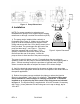
1. Introduction Thank you for your purchase of the Chem-Tech Series XP peristaltic pump from Pulsafeeder. We appreciate your decision to purchase a Pulsafeeder product. Please take this time to become familiar with your pump and the number of accessories that shipped with your product. The shipping box contains the following items: 1) Peristaltic pump comprising of: a) pump head and tube assembly, b) Snap-on rear rain guard (this can be found in the sealed bag that shipped with the product).
• • • • • • • • • WARNING: All pumps are factory tested with water. Remove tubing and thoroughly dry if the chemical being pumped will react with water (for example: sulfuric acid). WARNING: Only finger tighten plastic connections (Do not use a wrench). WARNING: Consult licensed plumber and electrician before installation to be sure to conform to local codes. CAUTION: Inspect tubing regularly for cracking or deterioration and replace as necessary.
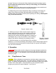
Vertical Mount Figure 1: Pump Dimensions 4. Installation NOTE: For pumps operating in swimming pool installations the pump is to be supplied by an isolating transformer or through a residual current device (RCD). Horizontal 1) The pump can be installed either vertically or horizontally (See Figure 2). Make sure to secure the pump on a flat level surface that will support 50-lbs (22kg) and secure with four .25-in (6mm) screws in the holes provided.
4) Apply Pipe tape to the injection fitting threads and install into piping system. Do not remove the plastic sleeve on the tip of the fitting; it is a functional part – see Figure 4. CAUTION: Inspect the piping system and eliminate piping cross-connections to prevent feeding chemical to areas not needing treatment. To install tubing remove the compression fitting’s coupling nut and slide onto tubing. Place tubing onto fitting and hand tighten the coupling nut.
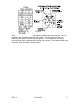
P P 1.. h Figure 6 As previously mentioned the mode selector switch has three positions. The offposition is the right side position of the switch. The switch also provides a manually-on function in the far left side position. This function is very useful when priming and/or replacing worn tubing in the pump. The middle position sets the pump in the automatic (Timer) mode. REV.
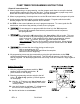
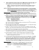
PUMP TIMER PROGRAMMING INSTRUCTIONS 1. Read all instructions first. 2. When programming or re-programming, use the program work sheet to set up the desired program before entering the steps into the timer. Seeing the program on paper may avoid errors and will make it easier to put the correct steps into the timer. 3. When re-programming, it is always best to use the ‘R’ reset button and re-program all cycles. 4. Avoid program sequences which overlap another program.
3. Slide the programming selector switch to center, ‘RUN’ position to check time setting. The colon’;’ will flash. Be certain that minutes do not change with each flash of the colon. If this condition occurs, an error has been made. Begin again at step #1. NOTE: 1 Setting the time in the above sequence will clear all programs, reset the programs as required. (Skip step #1 to correct the time setting without clearing programs). NOTE 2. Check the clock after completion of the time setting procedure.
12. Skip cycle button; ‘ may be used when you want to skip all program sequences programmed for the next day. Press the ‘ ’ button once, the ‘ ’ will appear in the lower right corner of the display. This will stop all program cycles from running the next calendar day (the day indicator ‘▲’ will flash during the day which is being skipped).
5.2. General DANGER: DO NOT ATTEMPT TO FEED CHEMICALS WITHOUT FIRST CONSULTING YOUR CHEMICAL FEEDER DEALER OR CHEMICAL SUPPLIER. To avoid running out of chemical, follow a regular schedule of monitoring chemical supply. CAUTION: Inspect peristaltic tubing frequently and replace when deterioration becomes apparent. Peristaltic tubing will eventually wear and break if neglected. This occurrence will cause chemical spillage and a potential for personal injury or damage to equipment.
6.1. Tubing Assembly Removal Always wear protective clothing and safety glasses when working on the chemical pump and refer to the chemical manufacturers’ safety precautions. 1) Remove the power to the pump and place the mode selector switch in the Off position. 2) Relieve the system pressure and the drain discharge and suction tubing. 3) Loosen coupling nuts and remove the tubing from suction and discharge ports. See figure 7a.
5) Remove pump head tube assembly by removing both connector fittings and pulling tubing straight out of the pump head. Tubing may retain a small amount of chemical. If the rotor assembly is removed, go to step #8. 6) Remove rotor assembly by pulling straight out of pump head. NOTE bearing lubrication every 500-hours; see section 6.2, “Tubing Assembly Installation and Lubrication”. 7) Clean any tubing debris from the rotor assembly and pump head. 6.2.
Note position of tube and rotor’s cut-away guide slot. Figure 9a: Rotor Alignment at Start of Tube Installation 3) Insert one connector end of the tubing assembly into the bottom retaining slot in the pump head. Insert the tube through the guide slot in the rotor. Using caution, intermittently jog the mode selector switch to from the on and off positions and feed the tube around the pump head as the guide slot rotates. Be very careful not to get any objects (fingers, ties, hair, etc.
Figure 9c: Finishing the New Tube Installation 6) Using the mode selector switch, run the pump for several revolutions and then fully tighten the thumb screws hand tight. 7) Return the pump to service by following the procedures in the installation section. 6.3.
7. Policies and Procedures 7.1. Manufacturers Product Warranty PULSAFEEDER warrants equipment of its manufacture to be free of defects in material or workmanship. Liability under this policy extends for 24-months from the date of shipment. The manufacturer’s liability is limited to repair or replacement of any failed equipment or part which is proven defective in material or workmanship upon manufacturers’ examination.
All material must be returned freight prepaid. All merchandise must be properly packaged and free of any corrosive, toxic or otherwise hazardous chemical. All items returned must reference Return Authorization number. 7.3. Credits No equipment will be accepted beyond six months after date of shipment from the factory. Only unused and undamaged equipment will be accepted for return to stock. All credits are based on acceptance of materials as new and unused by our inspection personnel.
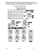
Appendix I. Pump Assembly and Wiring Diagram REV.
Maintenance Record Date REV.
EC Declaration of Conformity We, Pulsafeeder Inc., declare under sole responsibility that the Series XP metering pump, to which this declaration relates, is in sole conformity with relevant sections of the applicable EC standards and other normative documents listed on this document. If changes are made to the product which is covered by this declaration of conformity, the declaration of conformity is no longer valid.