
User manual

YR: Redundancy Modules Instruction Manual
YR: Bedienungsanleitung für Redundanzmodule
Product Description
The reliability of the DC voltages can be increased by using redundant systems. To achieve
redundancy, one extra power supply must be installed in order to deliver the required current in
case one power supply in the system fails. Each individual power supply must be isolated from the
others with diodes or mosfets. Redundancy modules have such components included and are
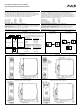
equipped with two input and one output channels. They can be used to build 1+1 and N+1
redundant systems.
The YR2 and YRM2 are redundancy modules for currents up to 20A and utilize diodes to isolate
the two inputs. The YRM2 has a monitoring circuitry included. LEDs and relay contacts signal
when one of the two input voltages is not in range due to a non-functioning or disconnected power
supply. The YR2 has no monitoring circuitry included and is the perfect fit when the power supply
itself is already equipped with a DC-OK contact. The YR40 and YR80 are high-current
redundancy modules for currents up to 40A and 80A. The novelty of these redundancy modules is
the utilization of mosfets instead of diodes for isolating the two input channels. This reduces the
heat generation and the voltage drop between input and output.
All redundancy modules do not require an additional auxiliary voltage and are self-sufficient even
in case of a short circuit across the output.
Gerätebeschreibung
Die Zuverlässigkeit von DC-Spannungen kann durch redundante Systeme erhöht werden. Um
eine Redundanz zu erreichen, muss ein zusätzliches Gerät in „Reserve“ installiert werden, das
dann den nötigen Laststrom zur Verfügung stellt, wenn ein Gerät im System ausfällt. Die
einzelnen Geräte müssen mittels Dioden oder Mosfets entkoppelt sein. Diese Bauteile sind in den
Redundanzmodulen integriert. Redundanzmodule haben zwei Eingänge und einen Ausgang und
können zum Aufbau von N+1 oder 1+1 redundanten Systemen verwendet werden.
Die YR2 und YRM2 Redundanzmodule sind für Ströme bis 20A geeignet und verwenden Dioden
zur Entkopplung. Das YRM2 hat eine Überwachung der Eingangsspannungen eingebaut. LEDs
und Relaiskontakte melden, wenn eine der beiden Eingangsspannungen unterhalb des zulässigen
Bereiches ist. Das YR2 hat keine Überwachungsfunktion eingebaut und kann verwendet werden,
wenn die Stromversorgung selbst bereits mit einem DC-OK Signal ausgestattet ist. YR40 und
YR80 sind Redundanzmodule für 40A und 80A Ausgangsstrom. Das Novum dieser Module sind
die Mosfets anstelle von Dioden zur Entkopplung der beiden Eingänge. Damit werden die
Wärmeentwicklung und der Spannungsabfall zwischen Eingang und Ausgang deutlich reduziert.
Alle Redundanzmodule benötigen keine zusätzliche Hilfsspannung und versorgen sich selbst,
auch im Falle eines Kurzschlusses am Ausgang.
Technical Data
1)
Technische Daten
1)
YR2.DIODE YRM2.DIODE YR40.241 YR80.241
Input Voltage Eingangsspannung nom. DC 12-48V
±25%
DC 24-48V
±25%
DC 24-28V
±30%
DC 24-28V
±30%
Input Voltage Range Eingangsspannungsbereich - 9-60Vdc 18-60Vdc 16.8-36.4Vdc 16.8-36.4Vdc
Output Current
2)
Normal Mode Ausgangsstrom
2)
Normalbetrieb nom. 20A 20A 40A 80A
Overload, Short-circuit Überlast, Kurzschluss max. 25A
3)
25A
3)
65A
3)
130A
3)
Input Current
2)
1+1 Redundancy Mode Eingangsstrom
2)
1+1 Redundanz Modus nom. 2x 12.5A 2x 12.5A 2x 20A 2x 40A
N+1 Redundancy Mode N+1 Redundanz Modus nom. 2x 10A 2x 10A 2x 20A 2x 40A
Peak Input Current (per input) Eingangsspitzenstrom (pro Eingang) max. 150A for 10ms 150A for 10ms 1000A for 1ms 1500A for 1ms
Reverse Current
4)
(per input) Rückwärtsstrom
4)
(pro Eingang) max. 2mA 2mA 1mA 1mA
Decoupling Element Entkopplungselement - Diode Diode Mosfet Mosfet
Voltage Drop
5)
(Input to Output) Spannungsabfall
5)
(Eingang zu Ausgang) typ. 850mV 850mV 140mV 95mV
Power Losses
5)
at full load Verlustleistung
5)
bei Volllast typ. 17W 18W 6.3W 8.3W
at no load im Leerlauf typ. 0W 1W 0.7W 0.7W
Low-Input-Voltage Alarm Contacts Eingangsspannungsüberwachungsrelais - no / nein yes / ja no / nein no / nein
Alarm threshold level (Alarm Meldeschwelle) nom. - 21.5V (±0.5V) - -
Operational Temperature Range Betriebstemperaturbereich nom. -40°C - +70°C -40°C - +70°C -40°C - +70°C -40°C - +70°C
Output Derating Ausgangsstromrücknahme +60°C to +70°C 0.5A/°C 0.5A/°C 0A/°C 0A/°C
Storage Temperature Range Lagertemperaturbereich nom. -40°C - +85°C -40°C - +85°C -40°C - +85°C -40°C - +85°C
Humidity
6)
Feuchte
6)
IEC 60068-2-30 5 - 95% r.H. 5 - 95% r.H. 5 - 95% r.H. 5 - 95% r.H.
Vibration Schwingen IEC 60068-2-6 2g 2g 2g 2g
Shock Schocken IEC 60068-2-27 30g 6ms, 20g 11ms 30g 6ms, 20g 11ms 30g 6ms, 20g 11ms 30g 6ms, 20g 11ms
Degree of Pollution (non-conductive) Verschmutzungsgrad (nicht leitend) EN 50178 / IEC 62103 2 2 2 2
Degree of Protection Schutzart EN 60529 IP20 IP20 IP20 IP20
Class of Protection Schutzklasse IEC 61140 III
7)
III
7)
III
7)
III
7)
Over-Temperature Protection Übertemperaturschutz OTP no / nein no / nein no / nein no / nein
Reverse Input Polarity Protection Eingangsverpolschutz - yes / ja yes / ja yes / ja yes / ja
Penetration Protection Fremdkörper Eindringschutz max. 3.5mm 3.5mm 3.5mm 3.5mm
Return Voltage Resistance
8)
Rückspeisefestigkeit
8)
max. 200Vdc 200Vdc 40Vdc 40Vdc
Isolation Against Housing Isolationsfestigkeit gegen Gehäuse min. 500Vac, 5MOhm 500Vac, 5MOhm 500Vac, 5MOhm 500Vac, 5MOhm
Quick-Connect Spring-Clamp Terminals Schnellanschluss Federkraftklemmen - yes / ja - - -
Screw Terminals Schraubklemmen - - yes / ja yes / ja yes / ja
Dimensions
9)
(WxHxD) Abmessungen
9)
(BxHxT) nom. 32x124x102mm 32x124x117mm 36x124x127mm 46x124x127mm
Weight Gewicht max. 290g, 0.64lb 350g, 0.77lb 340g, 0.75lb 440g, 0.97lb
Approvals Zulassungen - Æ 10) Æ10) Æ10) Æ10)
Limited Warranty Gewährleistung Years / Jahre 3 3 3 3
1) All parameters are specified at 24Vdc input voltage, nominal output current, 25°C ambient
and after a 5 minutes run-in time unless otherwise noted.
2) 50% higher currents up to 5s are allowed. The average (RMS) current is not allowed to
exceed 103% of the nominal current if repetitive pulses occur.
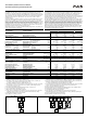
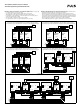
1+1 and N+1 Redundancy modes are explained in figures 1 to 2.
3) Ensure that the continuous output current does not exceed this value. Check the short-circuit
current of power sources. Do not use power sources which can deliver higher currents.
4) Over the entire temperature range.
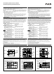
5) At nominal output current and symmetrical input currents. See figure 6 to 8.
6) Do not energize while condensation is present.
7) PE (Ground) connection optional but not required.
8) Loads such as decelerating motors and inductors can feed voltage back to the output of the
redundancy module. The figure represents the maximum allowed feed back voltage.
9) Depth without DIN-rail and connection terminals.
10) See datasheet or markings on the unit.
1) Alle Werte gelten bei 24Vdc Eingangsspannung, Nennausgangsstrom, 25°C Umgebungs-
temperatur und nach einer Aufwärmzeit von 5 Minuten, wenn nichts anderes angegeben ist.
2) 50% höhere Ströme sind bis zu 5s erlaubt. Der Mittelwert (RMS) des Stromes darf 103% des
Nennwertes nicht überschreiten, falls wiederholende Pulse auftreten.
1+1 und N+1 Redundanzmodus sind in den Bildern 1 bis 2 erklärt.
3) Der Dauerausgangsstrom darf auch im Fehlerfall diesen Wert nicht überschreiten. Verwenden
Sie keine Stromversorgungen die in der Summe höhere Ströme liefern können.
4) Über den gesamten Arbeitstemperaturbereich.
5) Bei Nennausgangsstrom und symmetrischen Eingangsströmen. Siehe auch Bilder 6 bis 8.
6) Nicht betreiben, solange das Gerät Kondensation aufweist.
7) PE Verbindung erlaubt, aber nicht erforderlich.
8) Bremsende Motoren oder Induktivitäten können Spannung zum Ausgang des
Redundanzmoduls rückspeisen. Der Wert gibt die max. zulässige Rückspeisespannung an.
9) Tiefe ohne DIN-Schiene und Anschlussklemmen.
10) Siehe Datenblatt oder Prüfzeichen auf dem Gerät.
Fig. 1 / Bild 1 1+1 Redundancy / 1+1 Redundanz Fig. 2 / Bild 2 N+1 Redundancy / N+1 Redundanz
AC
DC
AC
DC
Load
+
-
IN 1
OUT
IN 2
AC
DC
AC
DC
AC
DC
AC
DC
AC
DC
AC
DC
IN 1
OUT
IN 2 IN 1
OUT
IN 2 IN 1
OUT
IN 2
Load
+
-