
User manual

YR2.DIODE
Y-Series
10-60V, 20A, DUAL DECOUPLING MODULE
Nov 2006 / Rev. 1.0 DS-YR2.DIODE-EN
All parameters are specified at 24V, 20A output current, 25°C ambient and after a 5 minutes run-in time unless otherwise noted.
www.pulspower.com Phone +49 89 9278 0 Germany
4/16
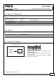
6. POWER LOSSES
Power losses
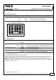
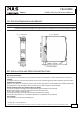
typ. 3.6W 10-60Vdc, 5A output current, see Fig. 6-1
typ. 7.85W 10-60Vdc, 10A output current, see Fig. 6-1
typ. 17.0W 10-60Vdc, 20A output current, see Fig. 6-1
Fig. 6-1 Power losses vs. output current
Power Losses, typ.
0
0 5 10 20
4
8
12
16
20
24W
25
A
15
Output Current
7. RELIABILITY
DC 24V
Lifetime expectancy min. > 25 years 40°C, input: 2x10A, output: 20A, no electrolytic capacitors involved
min. > 25 years 40°C, input: 2x5A, output: 10A, no electrolytic capacitors involved
min. > 25 years 25°C, input: 2x10A, output: 20A, no electrolytic capacitors involved
MTBF SN 29500, IEC 61709 46 500 000h 40°C, input: 2x10A, output: 20A
70 000 000h 25°C, input: 2x10A, output: 20A
MTBF MIL HDBK 217F 36 200 000h 40°C, input: 2x10A, output: 20A, Ground Benign GB40
41 100 000h 25°C, input: 2x10A, output: 20A, Ground Benign GB25
The Lifetime expectancy shown in the table indicates the operating hours (service life) and is determined by the
lifetime expectancy of the built-in electrolytic capacitors.
Lifetime expectancy is specified in operational hours. Lifetime expectancy is calculated according to the capacitor’s
manufacturer specification. The prediction model allows a calculation of up to 15 years from date of shipment.
MTBF stands for Mean Time Between Failure, which is calculated according to statistical device failures, and indicates
reliability of a device. It is the statistical representation of the likelihood of the unit to fail and does not necessarily
represent the life of a product.