
User manual
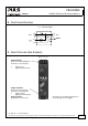

YR2.DIODE
Y-Series
10-60V, 20A, DUAL DECOUPLING MODULE
Nov 2006 / Rev. 1.0 DS-YR2.DIODE-EN
All parameters are specified at 24V, 20A output current, 25°C ambient and after a 5 minutes run-in time unless otherwise noted.
www.pulspower.com Phone +49 89 9278 0 Germany
3/16
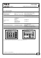
5. INPUT AND OUTPUT CHARACTERISTICS
Number of inputs
nom. 2
Number of outputs nom. 1
Input voltage nom. DC 24V
Input voltage range - 10-60Vdc
Voltage drop, input to output
typ. 0.85V At 2x10A, see Fig. 5-1
Input current max. 2x 12.5A Continuous, 1+1 Redundancy, see Fig. 5-2
max. 2x 10A Continuous, N+1 Redundancy, see Fig. 5-3
max. 1x 20A Continuous, Single use, see Fig. 5-4
Input current max. 2x 18.5A Up to 5s, 1+1 Redundancy, continuous, see Fig. 5-2
max. 2x 15A Up to 5s, N+1 Redundancy, continuous, see Fig. 5-3
max. 1x 30A Up to 5s, Single use, continuous, see Fig. 5-4
Peak input current
max. 150A Max. 10ms, per input
Output current max. 20A / 30A Normal mode, continuous / up to 5s
max.
25A / 37.5A
At overload or short-circuit, continuous / up to 5s
Reverse current
max. 2mA Per input, -25°C to +60°C
Reverse voltage max. 200Vdc Voltage applied to the output, continuously allowed
Note: Ensure that the continuous output current does not exceed 25A. Check the short-circuit current of the power
sources and if the power source can deliver more than 25A, use an appropriate fuse on the output.
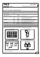
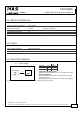
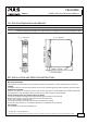
Fig. 5-1 Voltage Drop Fig. 5-2 1+1 Redundancy
Input to Output Voltage Drop, typ.
0
0 5 10 20
0.2
0.4
0.6
0.8
1.0
1.2V
25
A
15
Output Current
AC
DC
AC
DC
Load
+
-
IN 1
OUT
IN 2
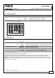
Fig. 5-3 N+1 Redundancy Fig. 5-4 Single use (redundant)
AC
DC
AC
DC
AC
DC
AC
DC
AC
DC
AC
DC
IN 1
OUT
IN 2
IN 1
OUT
IN 2
IN 1
OUT
IN 2
Load
+
-
Load
+
-
IN 1
OUT
IN 2
AC
DC
AC
DC
IN 1
OUT
IN 2