
User manual

YR2.DIODE
Y-Series
10-60V, 20A, DUAL DECOUPLING MODULE
Nov 2006 / Rev. 1.0 DS-YR2.DIODE-EN
All parameters are specified at 24V, 20A output current, 25°C ambient and after a 5 minutes run-in time unless otherwise noted.
www.pulspower.com Phone +49 89 9278 0 Germany
14/16
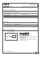
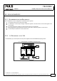
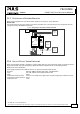
22.5. BATTERY BACK-UP
A battery back-up with 10A requires one 10A power supply and one YR2.DIODE decoupling module.
Please note:
Set output voltage of power supply to 26.5Vdc minimum to avoid that the charger current flows to the load instead of
charging the battery. Use a fuse between battery and YR2.DIODE!
Fig. 22-4 Wiring diagram, 10A Battery back-up
YR2.Diode
Decoupling
Module
+
-
OUT
+
-
IN 1
+
-
IN 2
L N PE
+ +
- -
QS10.241
Power
Supply
Adj
Overload
DCok
24V/10A
Failure
Monitor
10A
Load
optional
L
N
PE
24V Battery
I
Battery
Charger
+
-
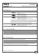
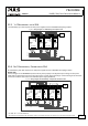
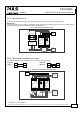
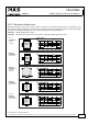
22.6. REDUNDANCY FOR SENSITIVE LOADS
Cost effective solution to get redundant power for a PLC or controller system.
Standard
design:
LoadPS1
PLC
PS2
Improved
approach:
Load
PLC
PS1
PS2
YR2
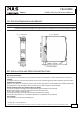
Fig. 22-5 Wiring diagram,
Redundancy for Sensitive Loads
Failure
Monitor
Sensitive
Load
e.g.
Controller
optional
L1 L2 L3 PE
+ +
- -
QT20.241
Power
Supply
Adj
Overload
DCok
24V/20A
L N PE
+ +
- -
QS5.241
Power
Supply
Adj
Overload
DCok
24V
5A
YR2.Diode
Decoupling
Module
+
-
OUT
+
-
IN 1
+
-
IN 2
I I I
L1
L2
PE
L3
I
N
Heavy
Loads
e.g. Motors