
Instructions

EN
YR2.DIODE Installation Manual
Product Description
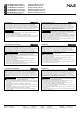
The YR2.DIODE is a redundancy module for building redundant power supply systems. It is equipped
with two input channels and one output. The two inputs are decoupled by diodes.
Intended Use
This device is designed for installation in an enclosure and is intended for commercial use, such as in
industrial control, process control, monitoring and measurement equipment or the like. Do not use this
device in equipment where malfunction may cause severe personal injury or threaten human life.
The redundancy module can be used with any type of power supply as long as the maximum output
current ratings are not exceeded. It is suitable for power supplies with continuous overload current as
well as any kind of intermittent (Hiccup) overload behavior.
Installation Instructions
Install the device in an enclosure providing protection against electrical, mechanical and fire hazards.
Do not ground or earth the positive output pole which could prevent redundancy in case of a ground
failure. Ground the negative output pole, when needed.
Use only power supplies with a negligible output ripple voltage in the low frequency range between
50Hz and 10kHz when used in marine applications according to the GL regulations.
Install the device onto a DIN-rail according to EN 60715 with the input terminals on the top of the
device.
Other mounting orientations require a reduction in output current.
Make sure that the wiring is correct by following all local and national codes. Use appropriate copper
cables that are designed for a minimum operating temperature of 60°C for ambient temperatures up to
+45°C, 75°C for ambient temperatures up to +60°C and 90°C for ambient temperatures up to +70°C.
Ensure that all strands of a stranded wire enter the terminal connection.
The device is designed for pollution degree 2 areas in controlled environments.
No condensation or
frost is allowed.
The enclosure of the device provides a degree of protection of IP20.
The input must be powered from a PELV or SELV source or an “Isolated Secondary Circuit” in order to
maintain a SELV or PELV output.
Check correct input polarity. The device will not operate when input voltage is reversed.
The device is designed as “Class of Protection III” equipment according to IEC 61140.
A PE (ground) connection is not required. However, connecting the chassis ground terminal to ground
can be beneficial to gain a high EMI immunity.
The device is designed for convection cooling and does not require an external fan. Do not obstruct
airflow and do not cover ventilation grid!
The device is designed for altitudes up to 6000m (19685ft). See additional requirements in the product
datasheet for use above 2000m (6560ft).
Keep the following minimum installation clearances: 40mm on top, 20mm on the bottom, 5mm left and
right side. Increase the 5mm to 15mm in case the adjacent device is a heat source. When the device
is permanently loaded with less than 50%, the 5mm can be reduced to zero.
The maximum surrounding air temperature is +70°C (+158°F). The operational temperature is the
same as the ambient or surrounding air temperature and is defined 2cm below the device.
The device is designed to operate in areas between 5% and 95% relative humidity.
Installation Instructions for Hazardous Location Areas
The device is suitable for use in Class I Division 2 Groups A, B, C, D locations and for use in Group II
Category 3 (Zone 2) environments.
Hazardous Location classification: ATEX: EPS 11 ATEX 1 312 X, II 3G EX ec IIC T4 Gc
WARNING EXPLOSION HAZARDS!
Substitution of components may impair suitability for this environment.
Do not disconnect the device unless power has been switched off or the area is known to be non-
hazardous.
A suitable enclosure must be provided for the end product which has a minimum protection of IP54
and fulfils the requirements of the EN 60079-0.
Functional Description
The device can supply any kind of loads, including unlimited capacitive and inductive loads.
Do not apply return voltages from the load to the output higher than 200Vdc.
Technical data
All values are typical figures specified at 24Vdc input voltage, 20A output
current, 25°C ambient temperature and after a 5 minutes run-in time
unless otherwise noted.
Input voltage DC 12 - 48V ±25%
Input voltage range 9 – 60Vdc
Input current 2x 10A Below +60°C ambient
2x 7.5A At +70°C ambient
2x 16A Up to 5 seconds
Output current 20A Continuous, <+60°C
15A Continuous, at +70°C
32A Up to 5 seconds
Maximum overload current 25A R.M.S. In any overload or short
circuit condition
Derate linearly between +60 and +70°C
Input to output voltage loss 780mV At 2x 5A input
850mV At 2x 10A input
Power losses 0W At no load
7.8W At 2x 5A input
17W At 2x 10A input
Temperature range -40°C to +70°C
Max. wire size (litz wire) 4mm²
Wire size AWG AWG 20-10
Max. wire diameter 2.8mm
Wire stripping length 10mm / 0.4inch
Size (wxhxd) 32x124x102mm Without DIN-rail
Weight 290g / 0.64lb
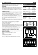
Functional diagram
+
-
+
-
+
-
Input 1
Input 2
PE
Output
Wiring scheme - 1+1 redundancy
L1
L2
PE
L3
Load
Failure
Monitor
I I I I I I
Power
Supply
Output
DC-
OK
L1 L2 L3
Input
+
-
+
-
o o
optional
Redundancy
Module
Output
Input
1
Input
2
+
-
+
-
+
-
Power
Supply
Output
DC-
OK
L1 L2 L3
Input
+
-
+
-
o o
Wiring scheme - n+1 redundancy
L1
L2
PE
L3
Load
Failure
Monitor
I I I
optional
I I I I I I
optional
I I I
Power
Supply
Output
DC-
OK
L1 L2 L3
Input
+
-
+
-
o o
Redundancy
Module
Output
Input
1
Input
2
+
-
+
-
+
-
Power
Supply
Output
DC-
OK
L1 L2 L3
Input
+
-
+
-
o o
Power
Supply
Output
DC-
OK
L1 L2 L3
Input
+
-
+
-
o o
Redundancy
Module
Output
Input
1
Input
2
+
-
+
-
+
-
Power
Supply
Output
DC-
OK
L1 L2 L3
Input
+
-
+
-
o o