
Datasheet

YR80.241
Y-Series
24-28V, 80A, DUAL REDUNDANCY MODULE
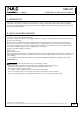
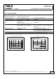
7. FUNCTIONAL DIAGRAM
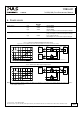
Fig. 7-1 Functional diagram
+
-
+
-
+
-
Input 1
control
control
Input 2
Chassis
Ground
Output
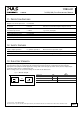
8. FRONT SIDE AND USER ELEMENTS
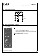
Fig. 8-1 Front side
A
Output Terminals (screw terminals)
B Chassis Ground Terminals
To be connected on the top side of the housing with a ring-type terminal
(ring cable lug) which is suitable for a M4 screw.
Connection of the chassis is optional and not required since the unit fulfils
the requirements according to protection class III.
C
Input Terminals for Input 1 (screw terminals)
D
Input Terminals for Input 2 (screw terminals)
Oct. 2010 / Rev. 1.0 DS-YR80.241-EN
All parameters are specified at 24V, 80A output current, 25°C ambient and after a 5 minutes run-in time unless otherwise noted
www.pulspower.com Phone +49 89 9278 0 Germany
7/17