
Datasheet

YR80.241
Y-Series
24-28V, 80A, DUAL REDUNDANCY MODULE
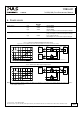
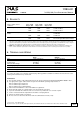
5. RELIABILITY
Input / output current
conditions
Input: 2x20A
Output: 40A
Input: 2x40A
Output: 80A
Input: 1x40A
Output: 40A
Lifetime expectancy
*) T.B.D. T.B.D. T.B.D. at 24V and 40°C
T.B.D. T.B.D. T.B.D. at 24V and 40°C
T.B.D. T.B.D. T.B.D. at 24V and 25°C
MTBF **) SN 29500, IEC
61709
T.B.D. T.B.D. T.B.D.
at 24V 40°C
T.B.D. T.B.D. T.B.D. at 24V 25°C
MTBF
**) MIL HDBK 217F T.B.D. T.B.D. T.B.D. Ground Benign GB40 (24Vand 40°C)
T.B.D. T.B.D. T.B.D. Ground Benign GB25 (24Vand 25°C)
*) The Lifetime expectancy shown in the table indicates the minimum operating hours (service life) and is determined by the lifetime
expectancy of the built-in electrolytic capacitors. Lifetime expectancy is specified in operational hours and is calculated according to the
capacitor’s manufacturer specification. The manufacturer of the electrolytic capacitors only guarantees a maximum life of up to 15 years
(131 400h). Any number exceeding this value is a calculated theoretical lifetime which can be used to compare devices.
**) MTBF stands for Mean Time Between Failure, which is calculated according to statistical device failures, and indicates reliability of a
device. It is the statistical representation of the likelihood of a unit to fail and does not necessarily represent the life of a product.
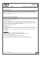
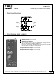
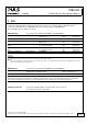
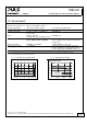
6. TERMINALS AND WIRING
Input Output
Type screw termination screw termination
Solid wire 0.5-16mm
2
0.5-35mm
2
Stranded wire 0.5-10mm
2
0.5-35mm
2
American Wire Gauge 22-8 AWG 20-2 AWG
Wire stripping length 12mm / 0.5inch 18mm / 0.7inch
Screwdriver 3.5mm slotted or Pozidrive No 2 5mm slotted or Pozidrive No 2
Recommended tightening torque 1.2Nm, 10.6lb.in 2.5Nm, 22lb.in
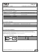
To connect the chassis, use a ring-type terminal (ring cable lug) which is suitable for a M4 screw and connect it to the
chassis ground terminal on top of the unit.
Instructions:
a) The external circuitry of all terminals must meet the safety requirements stipulated by IEC/EN/UL 60950-1: SELV.
b) Use appropriate copper cables that are designed for minimum operating temperatures of:
60°C for ambient up to 45°C and
75°C for ambient up to 60°C and
90°C for ambient up to 70°C minimum.
c) Follow national installation codes and installation regulations!
d) Ensure that all strands of a stranded wire enter the terminal connection!
e) Up to two stranded wires with the same cross section are permitted in one connection point.
f) Screws of unused terminal compartments should be securely tightened.
g) Ferrules are allowed, but not required.
h) Do not connect or disconnect the wires from the terminals below -25°C (-13°F).
Oct. 2010 / Rev. 1.0 DS-YR80.241-EN
All parameters are specified at 24V, 80A output current, 25°C ambient and after a 5 minutes run-in time unless otherwise noted
www.pulspower.com Phone +49 89 9278 0 Germany
6/17