
Datasheet

YR80.241
Y-Series
24-28V, 80A, DUAL REDUNDANCY MODULE
Oct. 2010 / Rev. 1.0 DS-YR80.241-EN
All parameters are specified at 24V, 80A output current, 25°C ambient and after a 5 minutes run-in time unless otherwise noted
www.pulspower.com Phone +49 89 9278 0 Germany
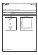
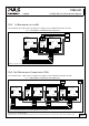
19.6. MOUNTING ORIENTATIONS
Mounting orientations other than input terminals on the bottom and output on the top require a reduction in
continuous output power or a limitation in the maximum allowed ambient temperature. The amount of reduction
influences the lifetime expectancy of the power supply. Therefore, two different derating curves for continuous
operation can be found below:
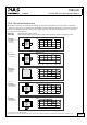
Curve A1 Recommended output current.
Curve A2 Max allowed output current (results in approximately half the lifetime expectancy of A1).
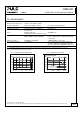
Fig. 19-3
Mounting
Orientation A
(Standard
orientation)
YR80
Redundancy
Module
OUTPUT
INPUTS
Output Current
0
20 30 40 50
70°C
20
40
60
80A
60
A
1
Ambient Temperature
Fig. 19-4
Mounting
Orientation B
(Upside down)
YR80
Redundancy
Module
OUTPUT
INPUTS
Output Current
0
20 30 40 50
70°C
20
40
60
80A
60
A
1
Ambient Temperature
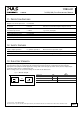
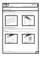
Fig. 19-5
Mounting
Orientation C
(Table-top
mounting)
Output Current
0
20 30 40 50
70°C
20
60
80A
60
40
A
1
A
2
Ambient Temperature
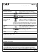
Fig. 19-6
Mounting
Orientation D
(Horizontal cw)
YR80
Redundancy
Module
OUTPUT
INPUTS
Output Current
0
20 30 40 50
70°C
20
60
80A
60
40
A
1
A
2
Ambient Temperature
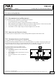
Fig. 19-7
Mounting
Orientation E
(Horizontal ccw)
YR80
Redundancy
Module
OUTPUT
INPUTS
Output Current
0
20 30 40 50
70°C
20
60
80A
60
40
A
1
A
2
Ambient Temperature
17/17