
Datasheet

YR80.241
Y-Series
24-28V, 80A, DUAL REDUNDANCY MODULE
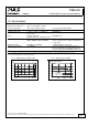
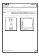
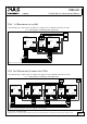
19.4. 1+1 REDUNDANCY UP TO 40A
1+1 Redundancy up to 40A requires two 40A power supplies and one YR80.241 redundancy modules.
Fig. 19-1 Wiring diagram, 1+1 Redundancy, 40A output current
L1
L2
PE
L3
YR80.241
Redundancy
Module
+
-
+
-
Input
1
Input
2
Output
L1 L2 L3 PE
QT40.241
40A Power Supply
+ +
- -
24V, 40A
Parallel Use
Single Use
DC-
OK
40A
Load
Failure
Monitor
I I I I I I
L1 L2 L3 PE
QT40.241
40A Power Supply
+ +
- -
24V, 40A
Parallel Use
Single Use
DC-
OK
Note: Use separate mains systems for each power supply whenever it is possible
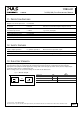
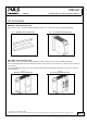
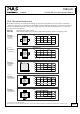
19.5. N+1 REDUNDANCY, EXAMPLE WITH 120A
n+1 Redundancy up to 120A requires four 40A power supplies and two YR80.241 redundancy module.
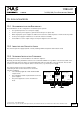
Fig. 19-2 Wiring diagram, n+1 Redundancy, 120A output current
YR80.241
Redundancy
Module
+
-
+
-
Input
1
Input
2
Output
L1 L2 L3 PE
QT40.241
40A Power Supply
+ +
- -
24V, 40A
Parallel Use
Single Use
DC-
OK
120A
Load
Failure
Monitor
16/17
I I I I I I
L1 L2 L3 PE
QT40.241
40A Power Supply
+ +
- -
24V, 40A
Parallel Use
Single Use
DC-
OK
YR80.241
Redundancy
Module
+
-
+
-
Input
1
Input
2
Output
L1 L2 L3 PE
QT40.241
40A Power Supply
+ +
- -
24V, 40A
Parallel Use
Single Use
DC-
OK
L1 L2 L3 PE
QT40.241
40A Power Supply
+ +
- -
24V, 40A
Parallel Use
Single Use
DC-
OK
I I I I I I
L1
L2
PE
L3
Note: Use separate mains systems for each power supply whenever it is possible
Oct. 2010 / Rev. 1.0 DS-YR80.241-EN
All parameters are specified at 24V, 80A output current, 25°C ambient and after a 5 minutes run-in time unless otherwise noted
www.pulspower.com Phone +49 89 9278 0 Germany