
Datasheet

YR80.241
Y-Series
24-28V, 80A, DUAL REDUNDANCY MODULE
19. APPLICATION NOTES
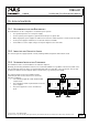
19.1. RECOMMENDATIONS FOR REDUNDANCY
Recommendations for the configuration of redundant power systems:
• Use separate input fuses for each power supply.
• Use three-phase power supplies to gain functional safety if one phase fails.
• When single-phase power supplies are utilized connect them to different phases or mains circuits if possible.
• Set the power supply in “Parallel-Use” mode if this feature is available
• It is desirable to set the output voltages of all power supplies to the same value.
19.2. INDUCTIVE AND CAPACITIVE LOADS
The unit is designed to supply any kind of loads, including unlimited capacitive and inductive loads.
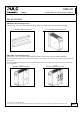
19.3. SIDEWARDS INSTALLATION CLEARANCES
The minimum clearance recommendations are defined in chapter 2.
Normally, the following installation clearance are recommended: 40mm on top, 20mm on the bottom, 5mm on the
left and right sides when the device is loaded permanently with more than 50% of the rated power. Increase this
clearance to 15mm in case the adjacent device is a heat source (e.g. another power supply).
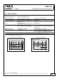
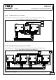
YR80.241
Redundancy
Module
+
-
+
-
Input
1
Input
2
Output
L1 L2 L3 PE
QT40.241
40A Power Supply
+ +
- -
24V, 40A
Parallel Use
Single Use
DC-
OK
L1 L2 L3 PE
QT40.241
40A Power Supply
+ +
- -
24V, 40A
Parallel Use
Single Use
DC-
OK
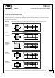
max.
40A
Load
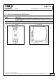
0mm0mm
The clearance between the power supplies and the
redundancy module can be reduced to zero under the
following conditions:
• 1+1 redundancy application with maximum 40A
output current.
• The redundancy module is placed between the two
power supplies.
• The power supplies are set into “Parallel Use”
mode
Oct. 2010 / Rev. 1.0 DS-YR80.241-EN
All parameters are specified at 24V, 80A output current, 25°C ambient and after a 5 minutes run-in time unless otherwise noted
www.pulspower.com Phone +49 89 9278 0 Germany
15/17