
Data Sheet

YR2.DIODE
Y-Series
DC12-48V (120V), 20A, DUAL REDUNDANCY MODULE
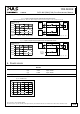
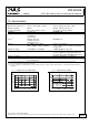
Fig. 3-2 Input to output voltage drop when both inputs draw current
(typical 1+1 redundant case, when the output voltages of the two units are equal or set into “parallel use” mode)
Voltage Drop, typ.
0mV
200mV
400mV
600mV
800mV
1000mV
5A 15A 20A10A
Output:
2x5A2x2.5A
Input:
2x10A2x7.5A
0
0
Input, Output Current
A
.
.
.
2
5
°
C
B
.
.
.
6
0
°
C
A
B
V
A
QS/QT10
24V,10A
+
-
QS/QT10
24V,10A
+
-
V
A
I
1
I
2
U
1
U
2
I
1
I
2
=
U
2
U
1
= Voltage Drop
U
1
=
U
OUT
-
Output
A
V
I
OUT
U
OUT
Variable
Load,
0-20A
YR2 / YRM2
Input 1
Input 2
Output
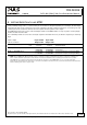
Fig. 3-3 Input to output voltage drop when only one input draws current
Voltage Drop
U
1
=
U
OUT
-
Not used or
power supply
with lower
voltage
V
A
QS/QT20
24V,20A
+
-
I
1
U
1
Output
A
V
I
OUT
U
OUT
Variable
Load,
0-20A
Input 1
Input 2
Output
YR2 / YRM2
Voltage Drop, typ.
0mV
200mV
400mV
600mV
800mV
1000mV
5A 15A 20
A
10A0
Output Current
A
.
.
.
2
5
°
C
B
.
.
.
6
0
°
C
A
B
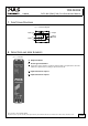
4. POWER LOSSES
DC 24V
Power losses typ.
7.8W input: 2x5A
typ.
8.5W
input: 1x10A
typ.
17.0W
input: 2x10A
Standby power losses typ. 0W at no output current
Fig. 4-1 Power losses
Power Losses, typ.
0
0 5 10 20
4
8
12
16
20
24W
25
A
15
Output Current
Apr. 2014 / Rev. 1.4 DS-YR2.DIODE-EN
All parameters are specified at 24V, 20A output current, 25°C ambient and after a 5 minutes run-in time unless otherwise noted
www.pulspower.com Phone +49 89 9278 0 Germany
5/19