
Data Sheet

YR2.DIODE
Y-Series
DC12-48V (120V), 20A, DUAL REDUNDANCY MODULE
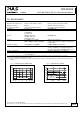
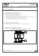
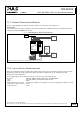
17.7. EXAMPLE: DECOUPLING OF BRANCHES
Buffer energy supplied from a DC-UPS or buffer module is not wasted in “power branches”.
Please note:
Set output voltage of the power supply to a level that the buffer unit or DC-UPS will not start unexpected. Take the
voltage drop of the YR2.DIODE into account.
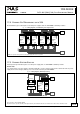
Fig. 17-5 Wiring diagram, decoupling of buffered branches
Buffered
Load
e.g.
Controller
optional
I I I
L1
L2
PE
L3
Load
e.g. Motor
Buffer
Module
+
-
Failure
Monitor
YR2.Diode
Redundancy
Module
+
-
OUT
+
-
IN 1
+
-
IN 2
L1 L2 L3 PE
+ +
- -
QT20.241
Power
Supply
Adj
Overload
DCok
24V,20A
Note: Use separate mains systems for each power supply whenever it is possible
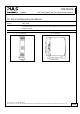
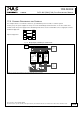
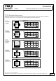
17.8. USE IN A TIGHTLY SEALED ENCLOSURE
When the redundancy module is installed in a tightly sealed enclosure, the temperature inside the enclosure will be
higher than outside. The inside temperature defines the ambient temperature for the redundancy module.
Results from such an installation:
Power supply is placed in the middle of the box, no other heat producer inside the box
Enclosure: Rittal Typ IP66 Box PK 9516 100, plastic, 110x180x165mm
Load: 24V, 16A; (=80%) load is placed outside the box
Input: 24Vdc
Temperature inside enclosure: 57.8°C (in the middle of the right side of the power supply with a distance of 2cm)
Temperature outside enclosure: 24.6°C
Temperature rise: 33.2K
Apr. 2014 / Rev. 1.4 DS-YR2.DIODE-EN
All parameters are specified at 24V, 20A output current, 25°C ambient and after a 5 minutes run-in time unless otherwise noted
www.pulspower.com Phone +49 89 9278 0 Germany
18/19