
Data Sheet

YR2.DIODE
Y-Series
DC12-48V (120V), 20A, DUAL REDUNDANCY MODULE
17. APPLICATION NOTES
17.1. RECOMMENDATIONS FOR REDUNDANCY
Recommendations for the configuration of redundant power systems:
• Use separate input fuses for each power supply.
• Use three-phase power supplies to gain functional safety if one phase fails.
• When single-phase power supplies are utilized connect them to different phases or mains circuits if possible.
• Set the power supply in “Parallel-Use” mode if this feature is available
• It is desirable to set the output voltages of all power supplies to the same value.
17.2. INDUCTIVE AND CAPACITIVE LOADS
The unit is designed to supply any kind of loads, including unlimited capacitive and inductive loads.
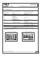
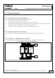
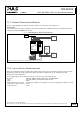
17.3. EXAMPLE: 1+1 REDUNDANCY UP TO 10A
1+1 Redundancy up to 10A requires two 10A power supplies and one YR2.DIODE redundancy module.
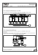
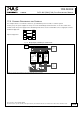
Fig. 17-1 Wiring diagram, 1+1 Redundancy, 10A output current
L N PE
+ +
- -
QS10.241
Power
Supply
Adj
Overload
DCok
24V,10A
Failure
Monitor
10A
Load
optional
I I
L
N
PE
L N PE
+ +
- -
QS10.241
Power
Supply
Adj
Overload
DCok
24V,10A
YR2.Diode
Redundancy
Module
+
-
OUT
+
-
IN 1
+
-
IN 2
Note: Use separate mains systems for each power supply whenever it is possible
Apr. 2014 / Rev. 1.4 DS-YR2.DIODE-EN
All parameters are specified at 24V, 20A output current, 25°C ambient and after a 5 minutes run-in time unless otherwise noted
www.pulspower.com Phone +49 89 9278 0 Germany
15/19