
Data Sheet

UF20.241
UF
-Series
24V, 20A, 200MS, BUFFER MODULE
Oct. 2016 / Rev. 2.0 DS-UF20.241-EN
All parameters are specified at 24V, 20A, 25°C ambient and after a 5 minutes run-in time unless otherwise noted.
www.pulspower.com Phone +49 89 9278 0 Germany
7/18
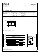
7. C
HARGING
T
IME
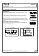
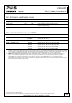
Charging of the internal capacitors is indicated by the status LED, which is flashing with a slow frequency (1.25Hz).
Charging
time Min. 20s
Initial charging
1)
Max. 29s
Initial charging
1)
Min. 15s
Re-charging
2)
Max. 21s
Re-charging
2)
1) Initial charging is the first charge after voltage is applied to the buffer module.
2) Re-charging is the charging of the internal capacitors after voltage interruptions shorter than 2minutes.
Fig. 7-1 Charging time, re-charging
Charge
20
0 5 10 30s
Charging Time
40
80
60
100%
15 20 25
max.
min.
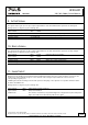
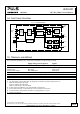
8. OPERATING DIAGRAMS
Fig. 8-1 Operating diagram Fig. 8-2 Signal schematic
Ready
t
Active
t
Optocoupler high ohmic
Optocoupler high ohmic
Optocoupler low ohmic
Optocoupler
low ohmic
V
Mains
t
V
Buffer
Capacitor
t
V
out
t
Charging Mode
LED
t
Buffer Mode
Hold-up Time Power Supply
Standby
Mode
10Hz1.25Hz
8 Ready
7 Active
6 +
5,1V
3mA
9 Inhibit
UF20