
Data Sheet

UF20.241
UF
-Series
24V, 20A, 200MS, BUFFER MODULE
Oct. 2016 / Rev. 2.0 DS-UF20.241-EN
All parameters are specified at 24V, 20A, 25°C ambient and after a 5 minutes run-in time unless otherwise noted.
www.pulspower.com Phone +49 89 9278 0 Germany
5/18
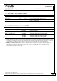
4. E
LECTRICAL
R
ATINGS
Supply
voltage Nom. DC 24V
-20%/+25%
Supply
voltage range
1)
Nom. 19.2 - 30Vdc
Normal
operating voltage range
2)
Typ. 23 – 30Vdc
Transfer voltage for switching
into
buffer mode
Typ.
Typ.
22.5Vdc
V
IN
– 1V
Back-up threshold jumper set to “22.5V fixed”
Back-up threshold jumper set to “V
IN
– 1V”
See also chapter 5.
Transfer voltage for switching
from buffer mode into power
supply mode
Typ.
Typ.
22.5Vdc
V
BUFFER
+ 1V
Back-up threshold jumper set to “22.5V fixed”
Back-up threshold jumper set to “V
IN
– 1V”
See also chapter 5.
Buffer volta
ge Typ. Same as the transfer voltage for switching into buffer mode.
Ripple and noise voltage
- in buffer mode
Max.
200mVpp
Generated by the buffer module.
Defined at 20Hz to 20MHz, 50Ohm
- in power supply mode The ripple and noise voltage is defined by the power supply.
Current consumption
Typ.
Min.
Max.
80mA
400mA
600mA
When capacitor is fully charged
During charging of the capacitors
During charging of the capacitors
Power dissipation
Typ. 1.9W When capacitor is fully charged
Buffer current
Min. 20A
Buffer current overload behavior
Electronically limited, buffering stops and capacitor gets discharged
below 17V. See Fig. 4-2.
Allowed voltage between
supply
voltage and chassis ground
Max. 60Vdc or
42.4Vac
Continuous, IEC 62477-1
Capacitive and inductive loads
No limitation
1) Supply Voltage Range:
At voltages within the input voltage range, control functions such as LEDs, monitoring features, relay contacts, etc. are functioning
normally. Within the input voltage range the unit can either be in power supply mode or in buffer mode.
2) Normal Operating Voltage Range:
The normal operating voltage range describes the supply voltage, which supports the full functionality of the buffer module (including
charging) but without entering the buffer mode.
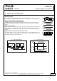
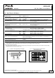
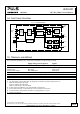
Fig. 4-1 Selection of an appropriate power supply Fig. 4-2 Output characteristic in buffer mode,
22.5V fixed mode, typ.
Internal
current
consumption
Current
consumption
for charging
Load
Current
Power
Supply
Current
Buffer Voltage
0
0 20
4
8
12
28V
16
20
32A124 8 16 24 28
Output Current
24
22.5V
Buffering stops
below 17V