
Data Sheet

UF20.241
UF
-Series
24V, 20A, 200MS, BUFFER MODULE
Oct. 2016 / Rev. 2.0 DS-UF20.241-EN
All parameters are specified at 24V, 20A, 25°C ambient and after a 5 minutes run-in time unless otherwise noted.
www.pulspower.com Phone +49 89 9278 0 Germany
18/18
25. W
IRING
D
IAGRAMS
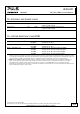
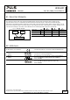
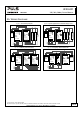
Fig. 25-1 General wiring diagram Fig. 25-2 Signals supplied from an external voltage source
L N PE
+
+
- -
Power
Supply
Adj
Overload
DC-OK
optional
L
N
PE
Load
+
-
Inhibit
Active
Relay, lamp or signal
Ready
Relay, lamp or signal
+ +
- -
UF20
Buffer
Module
Back-up
Threshold
Status
6 +
7 Active
8 Ready
9 Inhibit
L N PE
+ +
- -
Power
Supply
Adj
Overload
DC-OK
optional
L
N
PE
Load
+
-
Inhibit
Active
Relay, lamp or signal
Ready
Relay, lamp or signal
+ +
- -
UF20
Buffer
Module
Back-up
Threshold
Status
6 +
7 Active
8 Ready
9 Inhibit
External
Voltage Source
+
-
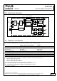
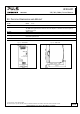
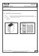
Fig. 25-3 Paralleling of buffer modules Fig. 25-4 Decoupling of buffered branches
L N PE
+ +
- -
Power
Supply
Adj
Overload
DC-OK
optional
L
N
PE
+ +
- -
UF20
Buffer
Module
Back-up
Threshold
Status
6 +
7 Active
8 Ready
9 Inhibit
Load
+
-
+ +
- -
UF20
Buffer
Module
Back-up
Threshold
Status
6 +
7 Active
8 Ready
9 Inhibit
L N PE
+ +
- -
Power
Supply
Adj
Overload
DC-OK
optional
L
N
PE
Un-
buffered
Load
+
-
YR2
Redund-
ancy
Module
+
-
OUT
+
-
IN 1
+
-
IN 2
Buffered
Load
+
-
+ +
- -
UF20
Buffer
Module
Back-up
Threshold
Status
6 +
7 Active
8 Ready
9 Inhibit