
Data Sheet

UF20.241
UF
-Series
24V, 20A, 200MS, BUFFER MODULE
Oct. 2016 / Rev. 2.0 DS-UF20.241-EN
All parameters are specified at 24V, 20A, 25°C ambient and after a 5 minutes run-in time unless otherwise noted.
www.pulspower.com Phone +49 89 9278 0 Germany
11/18
16. F
RONT
S
IDE AND
U
SER
E
LEMENTS
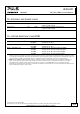
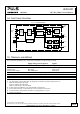
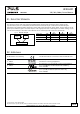
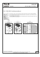
Fig. 16-1 Front side
A Supply Voltage Terminals
Quick-connect spring-clamp terminals, two per polarity
+ Positive supply voltage terminal
– Negative (return) supply voltage terminal
B Chassis Ground Terminal
Quick-connect spring-clamp terminals
Connection of the chassis to ground (earth) is optional
and only required for a few specific applications.
C Signal Connector
4-pole plug connector with screw termination comprises
the following signals:
- “Active” signal, for details see chapter 9.
- “Ready” signal, for details see chapter 10
- “Inhibit” input, for details see chapter 11
D Status LED
This green LED indicates that the following information:
- OFF: Capacitors are discharged or supply voltage is
below 22V.
- ON: Capacitors are fully charged
- Slow flashing (1.25Hz):
Capacitors are getting charged.
- Fast flashing (10Hz):
Capacitors are getting discharged.
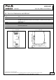
E Back-up Threshold Jumper
Option 1: Fixed mode (Jumper in position 2-3)
The unit switches to buffer mode as soon as the voltage falls
below 22.5V.
Option 2: Variable mode (Jumper in position 1-2)
Unit switches to buffer mode when input voltage decreases
by 1V. Voltage changes slower than 0.54V/s will be ignored if
the voltage is above 22.5V. Below 22.5V buffering starts
immediately.
For more details see chapter 5.