
Data Sheet
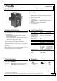

UF20.241
UF
-Series
24V, 20A, 200MS, BUFFER MODULE
Oct. 2016 / Rev. 2.0 DS-UF20.241-EN
All parameters are specified at 24V, 20A, 25°C ambient and after a 5 minutes run-in time unless otherwise noted.
www.pulspower.com Phone +49 89 9278 0 Germany
10/18
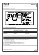
14. F
UNCTIONAL
D
IAGRAM
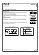
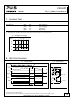
Fig. 14-1 Functional diagram
Buffer Capacitor
Charger &
Inrush Limiter
Buffer
Capacitor
Buffer Capacitor
Discharger
Status
LED
7 Active
6 (+)
Ready Monitor
+
-
Active Monitor
+
-
8 Ready
9 Inhibit
Opto-coupler
Buffer
Capacitor
Shut-Down
Input / Output
Voltage Monitor
Back-up
Level
Selector
Reverse-
Polarity
Protection
-
-
+
+
Safety and
Over-
Voltage
Protection
Chassis
Ground
Supply
Voltage
Opto-coupler
Opto-coupler
15. T
ERMINALS AND
W
IRING
The terminals are IP20 finger safe constructed and suitable for field and factory wiring.
Supply voltage, chassis ground Signals
Type
Quick-connect spring-clamp terminals Pluggable screw terminals
Solid wire
Max. 6mm
2
Max. 2.5mm
2
Stranded wire
Max. 4mm
2
Max. 2.5mm
2
American Wire Gauge
Max. AWG 20-10 AWG 22-14
Max. wire diameter
Max. 2.8mm (including ferrules) 2.25mm (including ferrules)
Wire stripping length
Typ. 10mm / 0.4inch 6mm / 0.25inch
Tightening torque
Not applicable 0.4Nm / 3.5lb.inch
Screwdriver
Not applicable 3mm slotted
Instructions:
a)
Use appropriate copper cables that are designed for minimum operating temperatures of:
60°C for ambient up to 45°C and
75°C for ambient up to 60°C and
90°C for ambient up to 70°C minimum.
b)
Follow national installation codes and installation regulations!
c)
Ensure that all strands of a stranded wire enter the terminal connection!
d)
Unused terminal compartments should be securely tightened or closed.
e)
Ferrules are allowed.