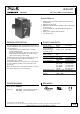
UF20.241 24V, 20A, 200MS, BUFFER MODULE UF-Series BUFFER MODULE Buffering with electrolytic capacitors instead of lead acid batteries Buffering of 24V loads Minimum hold-up time 0.
UF20.241 24V, 20A, 200MS, BUFFER MODULE UF-Series INDEX Page 1. 2. 3. 4. 5. 6. 7. 8. 9. 10. 11. 12. 13. 14. Intended Use .......................................................3 Installation Notes ................................................3 Functional Description ........................................4 Electrical Ratings .................................................5 Selection of the Back-up Threshold Voltage .....6 Buffer Time ..........................................................
UF20.241 UF-Series 24V, 20A, 200MS, BUFFER MODULE 1. INTENDED USE This device is designed for installation in an enclosure. Use an appropriate enclosure which protects against mechanical, electrical and fire hazards. This device is intended for professional use in areas such as in industrial control, office, communication, and instrumentation equipment. Do not use this device in equipment or systems where malfunction may cause severe personal injury or threaten human life. 2.
UF20.241 24V, 20A, 200MS, BUFFER MODULE UF-Series 3. FUNCTIONAL DESCRIPTION Working principle When the power supply provides sufficient voltage, the buffer module stores energy in the integrated electrolytic capacitors. In case of a voltage dip or loss, this energy is released to the DC bus in a regulated process. Bridges mains faults without interruption Statistic show that 80% of all mains fault lasts less than 0.2s. These mains faults are completely bridged by the buffer unit.
UF20.241 24V, 20A, 200MS, BUFFER MODULE UF-Series 4. ELECTRICAL RATINGS Supply voltage Supply voltage range1) Normal operating voltage range2) Transfer voltage for switching into buffer mode Nom. Nom. Typ. Typ. Typ. Transfer voltage for switching from buffer mode into power supply mode Typ. Typ. Buffer voltage Ripple and noise voltage - in buffer mode - in power supply mode Current consumption Typ. Max.
UF20.241 24V, 20A, 200MS, BUFFER MODULE UF-Series 5. SELECTION OF THE BACK-UP THRESHOLD VOLTAGE The buffer behavior can be selected with the back-up jumper selector between “Fixed Mode” and “Variable Mode”. Fixed Mode: (Jumper in position „2-3“ or „22.5V fixed”) If the supply output voltage falls below 22.5V, buffering starts and the supply voltage will be kept at this level.
UF20.241 24V, 20A, 200MS, BUFFER MODULE UF-Series 7. CHARGING TIME Charging of the internal capacitors is indicated by the status LED, which is flashing with a slow frequency (1.25Hz). Charging time Min. Max. Min. Max. 20s 29s 15s 21s Initial charging 1) Initial charging 1) Re-charging 2) Re-charging 2) 1) Initial charging is the first charge after voltage is applied to the buffer module. 2) Re-charging is the charging of the internal capacitors after voltage interruptions shorter than 2minutes. Fig.
UF20.241 24V, 20A, 200MS, BUFFER MODULE UF-Series 9. ACTIVE SIGNAL The signal “Active” (pin 7) is an opto-coupler output which is low ohmic while buffer capacitors are discharged. Wiring scheme see Fig. 8-2, Fig. 25-1 and Fig. 25-2. Signal voltage Signal current Voltage drop across opto-coupler Leakage current Isolation voltage Max. Max. 35Vdc 10mA 0.9V / 3V Max. 50µA See chapter 21. Voltage between pin 6 and 7 At 1mA / 5mA while opto-coupler is low ohmic While opto-coupler is high ohmic 10.
UF20.241 24V, 20A, 200MS, BUFFER MODULE UF-Series 12. EFFICIENCY AND POWER LOSSES Efficiency Typ. >99% Power losses Typ. 1.9W Power supply mode, 20A output current, capacitors fully charged Power supply mode, 0A output current, capacitors fully charged 13.
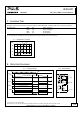
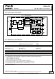
UF20.241 24V, 20A, 200MS, BUFFER MODULE UF-Series 14. FUNCTIONAL DIAGRAM Fig. 14-1 Functional diagram + Supply + Voltage - Status LED Buffer Capacitor Charger & Inrush Limiter ReversePolarity Protection Safety and OverVoltage Protection Buffer Capacitor Discharger Buffer Capacitor Shut-Down Buffer Capacitor Chassis Ground 6 (+) 9 Inhibit Opto-coupler Input / Output Voltage Monitor Back-up Level Selector + - 8 Ready Ready Monitor Opto-coupler + - 7 Active Active Monitor Opto-coupler 15.
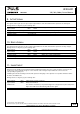
UF20.241 24V, 20A, 200MS, BUFFER MODULE UF-Series 16. FRONT SIDE AND USER ELEMENTS Fig. 16-1 Front side A Supply Voltage Terminals Quick-connect spring-clamp terminals, two per polarity + Positive supply voltage terminal – Negative (return) supply voltage terminal B Chassis Ground Terminal Quick-connect spring-clamp terminals Connection of the chassis to ground (earth) is optional and only required for a few specific applications.
UF20.241 24V, 20A, 200MS, BUFFER MODULE UF-Series 17. EMC The buffer module is suitable for applications in industrial environment as well as in residential, commercial and light industry environment.
UF20.241 24V, 20A, 200MS, BUFFER MODULE UF-Series 18. ENVIRONMENT Operational temperature *) Storage temperature Humidity **) Vibration sinusoidal Vibration random Shock Altitude Over-voltage category Degree of pollution LABS compatibility -25°C to +70°C (-13°F to 158°F) -40 to +70°C (-40°F to 158°F) For storage and transportation 5 to 95% r.H. IEC 60068-2-30 2-17.8Hz: ±1.6mm; 17.8-500Hz: 2g IEC 60068-2-6 2 hours / axis 0.
UF20.241 24V, 20A, 200MS, BUFFER MODULE UF-Series 21. DIELECTRIC STRENGTH The signal port (active and ready signal and inhibit input) is floating and separated from the supply voltage. Type and factory tests are conducted by the manufacturer. Field tests may be conducted in the field using the appropriate test equipment which applies the voltage with a slow ramp (2s up and 2s down). Connect all poles of the power port terminals together as well as all poles of the signal port before conducting the test.
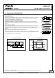
UF20.241 UF-Series 24V, 20A, 200MS, BUFFER MODULE 23. PHYSICAL DIMENSIONS AND WEIGHT Width Height Depth Weight DIN-rail Housing material Installation clearances 64mm 2.13’’ 124mm 4.88’’ 102mm 4.02’’ The DIN-rail height must be added to the unit depth to calculate the total required installation depth. 740g / 1.63lb Use 35mm DIN-rails according to EN 60715 or EN 50022 with a height of 7.5 or 15mm. Body: Aluminium alloy Cover: Zinc-plated steel See chapter 2 Fig. 23-1 Front view Fig.
UF20.241 24V, 20A, 200MS, BUFFER MODULE UF-Series 24. ACCESSORIES 24.1. ZM1.WALL - WALL MOUNTING BRACKET This bracket is used to mount the buffer module on a wall without utilizing a DIN-Rail. The two aluminum brackets and the black plastic slider of the unit have to be detached, so that the steel brackets can be mounted. Fig. 24-1 Wall mounting Fig. 24-2 Mounting Dimensions - Wall mounting bracket Oct. 2016 / Rev. 2.0 DS-UF20.
UF20.241 24V, 20A, 200MS, BUFFER MODULE UF-Series 24.2. ZM14.SIDE - SIDE MOUNTING BRACKET This bracket is used to mount the buffer module sideways with or without utilizing a DIN-Rail. The two aluminum brackets and the black plastic slider of the unit have to be detached, so that the steel brackets can be mounted. For sideway DIN-rail mounting, the removed aluminum brackets and the black plastic slider need to be mounted on the steel bracket. Fig. 24-3 Side mounting without DINrail brackets Fig.
UF20.241 24V, 20A, 200MS, BUFFER MODULE UF-Series 25. WIRING DIAGRAMS optional External Voltage Source Inhibit Ready Relay, lamp or signal Active Relay, lamp or signal 7 Active optional -- +- +- IN 1 IN 2 Adj DC-OK Overload UF20 Back-up Buffer Threshold Module +Buffered Load 6 + OUT + - optional Oct. 2016 / Rev. 2.0 DS-UF20.241-EN All parameters are specified at 24V, 20A, 25°C ambient and after a 5 minutes run-in time unless otherwise noted. www.pulspower.