
Data Sheet

UB10.241
U–Series
24V, 10A, DC-UPS
Mar. 2019 / Rev. 1.3a DS-UB10.241-EN
All parameters are specified at an input voltage of 24V, 10A output load, 25°C ambient and after a 5 minutes run-in time
unless otherwise noted. It is assumed that the input power source can deliver a sufficient output current.
www.pulspower.com Phone +49 89 9278 0 Germany
6/24
8. B
ATTERY
I
NPUT
The DC-UPS requires one 12V VRLA battery to buffer the 24V output.
Battery voltage nom. DC 12V Use one maintenance-free 12V VRLA lead acid battery or
one battery module which is listed in the chapter
accessories.
Battery voltage range
9.0 – 15.0V
Continuously allowed, except deep discharge protection
max. 35Vdc Absolute maximum voltage with no damage to the unit
typ. 7.4V Above this voltage level battery charging is possible
Allowed battery sizes
min. 3.9Ah
max. 40Ah
Internal battery resistance
max. 100mOhm See individual battery datasheets for this value
Battery charging method CC-CV Constant current, constant voltage mode
Battery charging current (CC-mode) nom. 1.5A Independent from battery size,
max. 1.7A Corresponding 24V input current see Fig. 8-2
End-of-charge-voltage (CV-mode)
13.4-13.9V Adjustable, see chapter 14
Battery charging time typ. 5h *) For a 7Ah battery
typ. 17h *) For a 26Ah battery
Battery discharging current **)
typ. 21A Buffer mode, 10A output current, 11.5V on the battery
terminal of the DC-UPS, see Fig. 8-1 for other parameters
typ. 0.3A Buffer mode, 0A output current
max. 50µA At no input, buffering had switched off, all LEDs are off
typ. 270mA At no input, buffering had switched off, yellow LED
shows “buffer time expired” (max. 15 minutes)
Deep discharge protection ***)
typ. 10.5V At 0A output current
typ. 9.0V At 10A output current
*) The charging time depends on the duration and load current of the last buffer event. The numbers in the table represent a
fully discharged battery. A typical figure for a buffer current of 10A is 3h 20Min. for a 7Ah battery.
**) The current between the battery and the DC-UPS is more than twice the output current. This is caused by boosting the 12V
battery voltage to a 24V level. This high current requires large wire gauges and short cable length for the longest possible
buffer time. The higher the resistance of the connection between the battery and the DC-UPS, the lower the voltage on the
battery terminals which increases the discharging current. See also chapter 25 for more installation instructions.
***) To ensure longest battery lifetime, the DC-UPS has a battery deep discharge protection feature included. The DC-UPS stops
buffering when the voltage on the battery terminals of the DC-UPS falls below a certain value. The yellow LED will show
“buffer time expired” for a period of 15 minutes after the unit stopped buffering.
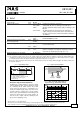
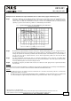
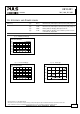
Fig. 8-1 Battery discharging current
vs. output current, typ.
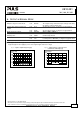
Fig. 8-2 Required input current vs. input
voltage for battery charging
Battery Current
0
0
10
20
5
15
25
30A
2.5 7.5 10 15A12.55
Output Current
Voltage on
battery terminal
of the DC-UPS:
A: 10.5V
B: 11V
C: 12V
A B C
Input Current
0
23
0.5
1.0
0.25
0.75
1.25
1.5A
Input Voltage
24 25 26
28V
max. (battery charging current 1.7A)
27
typ. (battery charging current 1.5A)