
Data Sheet

UB10.241
U–Series
24V, 10A, DC-UPS
Mar. 2019 / Rev. 1.3a DS-UB10.241-EN
All parameters are specified at an input voltage of 24V, 10A output load, 25°C ambient and after a 5 minutes run-in time
unless otherwise noted. It is assumed that the input power source can deliver a sufficient output current.
www.pulspower.com Phone +49 89 9278 0 Germany
15/24
15. T
ERMINALS AND
W
IRING
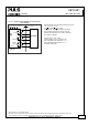
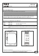
Power terminals Signal terminals
Type
Bi-stable, quick-connect spring-
clamp terminals. IP20 Finger-
touch-proof. Suitable for field-
and factory installation. Shipped
in open position.
Plug connector with screw terminal. Finger-touch-proof
construction with captive screws for 3.5mm slotted
screwdriver. Suitable for field- and factory installation.
Shipped in open position. To meet GL requirements,
unused terminal compartments should be closed.
Solid wire 0.5-6mm
2
0.2-1.5mm
2
Stranded wire 0.5-4mm
2
0.2-1.5mm
2
AWG 20-10AWG 22-14AWG
Ferrules Allowed, but not required Allowed, but not required
Pull-out force 10AWG:80N, 12AWG:60N,
14AWG:50N, 16AWG:40N
according to UL486E
Not applicable
Tightening torque
Not applicable
0.4Nm, 3.5lb.in
Wire stripping length 10mm / 0.4inch 6mm / 0.24inch
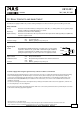
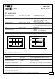
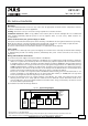
Fig. 15-1 Spring-clamp terminals, connecting a wire
Instructions:
a) Use appropriate copper cables, that are designed
for an operating temperature of 60°C
b) Follow national installation codes and regulations!
c) Ensure that all strands of a stranded wire enter the
terminal connection!
d) Up to two stranded wires with the same cross
section are permitted in one connection point
16. R
ELIABILITY
Lifetime expectancy min. 137 400h At 10A output current, 40°C
min. > 15 years At 5A output current, 40°C
min. > 15 years At 10A output current, 25°C
MTBF SN 29500, IEC 61709 886 000h At 10A output current, 40°C
1 482 000h At 10A output current, 25°C
MTBF MIL HDBK 217F 397 900 At 10A output current , 40°C, ground benign GB40
545 000 At 10A output current , 25°C, ground benign GB25
The Lifetime expectancy shown in the table indicates the operating hours (service life) and is determined by the
lifetime expectancy of the built-in electrolytic capacitors. Lifetime expectancy is specified in operational hours.
Lifetime expectancy is calculated according to the capacitor’s manufacturer specification. The prediction model allows
a calculation of up to 15 years from date of shipment.
MTBF stands for Mean Time Between Failure, which is calculated according to statistical device failures and indicates
reliability of a device. It is the statistical representation of the likelihood of a unit to fail and does not necessarily
represent the life of a product.