
Data Sheet
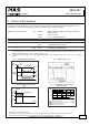

UB10.241
U–Series
24V, 10A, DC-UPS
Mar. 2019 / Rev. 1.3a DS-UB10.241-EN
All parameters are specified at an input voltage of 24V, 10A output load, 25°C ambient and after a 5 minutes run-in time
unless otherwise noted. It is assumed that the input power source can deliver a sufficient output current.
www.pulspower.com Phone +49 89 9278 0 Germany
10/24
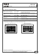
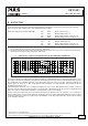
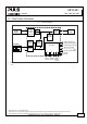
11. F
UNCTIONAL
D
IAGRAM
Fig. 11-1 Functional diagram
DC
-UPS Control Unit
Battery
Charger
Battery
Tester
Cut
-off
Relay
Battery
+
-
12V Battery
24V
Power
Supply
Input
-
+
-
+
Reverse
Polarity
Protection
Input Fuse
&
*
(5)
(6)
Ready
Contact
(
1) (
2)
Buffering
Contact
(3
) (4
)
Electronic
Current
Limiter
Buffered
Load
+
-
Output
Controller
Diagnosis LED
(yellow
)
Check Wiring LED (red)
Status LED (green)
Buffer-time Limiter
10s, 30s, 1m, 3m, 10m,
End-of-charge Voltage
Inhibit -
Inhibit +
Replace
Battery
Contact
Step-up
Converter
(7)
(8)
*) Return current protection; This feature utilizes a Mosfet instead of a diode in order to minimize the voltage drop and power
losses.