UB10.241 24V, 10A, DC-UPS U–Series DC-UPS CONTROL UNIT ■ ■ ■ ■ ■ ■ ■ ■ ■ Requires Only One 12V Battery for a 24V Output Stable Output Voltage in Buffer Mode Superior Battery Management for Longest Battery Life Comprehensive Diagnostic and Monitoring Functions Replace Battery Signal Included Electronically Overload and Short Circuit Protected 50% Power Reserves Selectable Buffer Time Limiter 3 Year Warranty 1. GENERAL DESCRIPTION 2.
UB10.241 24V, 10A, DC-UPS U–Series INDEX 1. 2. 3. 4. 5. 6. 7. 8. 9. 10. 11. 12. 13. 14. 15. 16. PAGE General Description ............................................1 Short-form Data ..................................................1 Order Numbers ....................................................1 Markings ..............................................................1 Input ....................................................................3 Output in Normal Mode ..................................
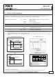
UB10.241 24V, 10A, DC-UPS U–Series 5. INPUT nom. nom. Input voltage Input voltage ranges DC 24V 22.5 to 30Vdc 30 to 35Vdc 35Vdc 0 to 22.5Vdc Allowed input voltage ripple max. Allowed voltage between input and earth (ground) Turn-on voltage max. Input current **) typ. 1.5Vpp 1Vpp 60Vdc or 42.4Vac 22.8Vdc max. typ. typ. 23Vdc 120mA 1.1A External capacitors on the input Continuous operation, see Fig.
UB10.241 24V, 10A, DC-UPS U–Series 6. OUTPUT IN NORMAL MODE Output voltage in normal mode nom. DC 24V Voltage drop between input and output max. 0.3V max. max. nom. nom. min. max. 0.45V 20mVpp 15A 360W 17.9A 21A No limitation Ripple and noise voltage Output current Output power Short-circuit current Capacitive and inductive loads *) The output voltage follows the input voltage reduced by the input to output voltage drop. At 10A output current, see Fig.
UB10.241 24V, 10A, DC-UPS U–Series 7. OUTPUT IN BUFFER MODE If the input voltage falls below a certain value (transfer threshold level), the DC-UPS starts buffering without any interruption or voltage dips. Buffering is possible even if the battery is not fully charged. Output voltage in buffer mode nom. Transfer threshold for buffering Ripple and noise voltage Output current typ. max. nom. Short-circuit current min. max.
UB10.241 24V, 10A, DC-UPS U–Series 8. BATTERY INPUT The DC-UPS requires one 12V VRLA battery to buffer the 24V output. Battery voltage nom. Battery voltage range typ. typ. typ. 9.0 – 15.0V 35Vdc 7.4V 3.9Ah 40Ah 100mOhm CC-CV 1.5A 1.7A 13.4-13.9V 5h *) 17h *) 21A typ. max. typ. 0.3A 50µA 270mA typ. typ. 10.5V 9.0V max. typ. min. max. max. Allowed battery sizes Internal battery resistance Battery charging method Battery charging current (CC-mode) nom. max.
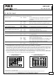
UB10.241 24V, 10A, DC-UPS U–Series 9. BUFFER TIME The buffer time depends on the capacity and performance of the battery as well as the load current. The diagram below shows the typical buffer times of the standard battery modules. Buffer time with battery module UZK12.071 Buffer time with battery module UZK12.261 *) min. min. typ. typ. min. min. typ. typ. 19’12’’ 5’42’’ 21’30’’ 6’45’’ 99’30’’ 39’ 130’ 55’ At 5A output current *) At 10A output current *) At 5A output current, see Fig.
UB10.241 24V, 10A, DC-UPS U–Series Example how to determine the expected buffer time for other battery types and battery sizes: Step 1 Check the datasheet of the battery which is planned to be used and look for the discharging curve. Sometimes, the individual discharging curves are marked with relative C-factors instead of current values. This can easily be converted. The C-factor needs to be multiplied with the nominal battery capacity to get the current value. E.g.: 0.6C on a 17Ah battery means 10.2A.
UB10.241 24V, 10A, DC-UPS U–Series 10. EFFICIENCY AND POWER LOSSES Efficiency Power losses typ. typ. typ. typ. 97.8% 2.9W 5.5W 5.0W typ. 2.1W typ. 18.5W Normal mode, 10A output current, battery fully charged Normal mode, 0A output current, battery fully charged Normal mode, 10A output current, battery fully charged During battery charging, 0A output current During battery charging, to be added to power losses in normal mode, fig.Fig. 10-2 Buffer mode, 10A output current Fig.
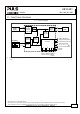
UB10.241 24V, 10A, DC-UPS U–Series 11. FUNCTIONAL DIAGRAM Fig.
UB10.241 24V, 10A, DC-UPS U–Series 12. CHECK WIRING AND BATTERY QUALITY TESTS The DC-UPS is equipped with an automatic “Check Wiring” and “Battery Quality” test. “Check Wiring” test: Under normal circumstances, an incorrect or bad connection from the battery to the DC-UPS or a missing (or blown) battery fuse would not be recognized by the UPS when operating in normal mode. Only when back up is required would the unit not be able to buffer. Therefore, a “check wiring” test is included in the DC-UPS.
UB10.241 24V, 10A, DC-UPS U–Series 13. RELAY CONTACTS AND INHIBIT INPUT The DC-UPS is equipped with relay contacts and signal inputs for remote monitoring and controlling of the unit. Relay contacts: Ready: Contact is closed when battery is charged more than 85%, no wiring failure are recognized, input voltage is sufficient and inhibit signal is not active. Buffering: Contact is closed when unit is buffering.
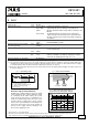
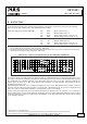
UB10.241 24V, 10A, DC-UPS U–Series - Input DCUPS + + Fig. 13-1 Contact control drawing for use in Haz-Loc environments - Output 1 Ready 2 3 Buffering Replace Battery Battery + Hazardous Location 4 5 6 Non Hazardous Location Isc Voc Isc Voc Isc Voc Apparatus Selected barriers must have entity parameters such that Voc < V max, Isc < I max, Ca > Ci + Ccable, La > Li + Lcable.
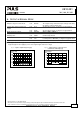
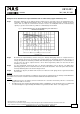
UB10.241 24V, 10A, DC-UPS U–Series 14. FRONT SIDE USER ELEMENTS A Power Port Quick-connect spring-clamp terminals, connection for input voltage, output voltage and battery B Signal Port Plug connector with screw terminals, inserted from the bottom. Connections for the Ready, Buffering, Replace Battery relay contacts and for the Inhibit input. See details in chapter 13.
UB10.241 24V, 10A, DC-UPS U–Series 15. TERMINALS AND WIRING Type Solid wire Stranded wire AWG Ferrules Pull-out force Tightening torque Wire stripping length Power terminals Bi-stable, quick-connect springclamp terminals. IP20 Fingertouch-proof. Suitable for fieldand factory installation. Shipped in open position. 2 0.5-6mm 2 0.5-4mm 20-10AWG Allowed, but not required 10AWG:80N, 12AWG:60N, 14AWG:50N, 16AWG:40N according to UL486E Not applicable 10mm / 0.
UB10.241 24V, 10A, DC-UPS U–Series 17. EMC The unit is suitable for applications in industrial environment as well as in residential, commercial and light industry environment without any restrictions. CE mark is in conformance with EMC guideline 89/336/EEC and 93/68/EEC and the low-voltage directive (LVD) 73/23/EEC, 93/68/EEC. A detailed EMC Report is available on request.
UB10.241 24V, 10A, DC-UPS U–Series 18. ENVIRONMENT Operational temperature -25°C to +70°C (-13° to +158°F) Derating 0.43A/°C 0.25A/°C Storage temperature Humidity -40 to +85°C (-40° to +185°F) 5 to 95% r.H. Vibration sinusoidal Shock Altitude Over-voltage category 2-17.8Hz: ±1.6mm; 17.8-500Hz: 2g 30g 6ms, 20g 11ms 0 to 6000m II II 2 Degree of pollution For the DC-UPS control unit. Keep battery in a cooler environment! +60°C to +70°C (+140°F to +158°F), normal mode see Fig.
UB10.241 24V, 10A, DC-UPS U–Series 20. SAFETY Output voltage SELV IEC/EN 60950-1 PELV EN 60204-1, EN 50178, IEC 60364-4-41 Max. allowed voltage between any input, output or signal pin and ground: 60Vdc or 42.
UB10.241 24V, 10A, DC-UPS U–Series 23. USED SUBSTANCES The unit does not release any silicone and is suitable for the use in paint shops. The unit conforms to the RoHS directive 2002/96/EC. Electrolytic capacitors included in this unit do not use electrolytes such as Quaternary Ammonium Salt Systems. Plastic housings and other molded plastic materials are free of halogens, wires and cables are not PVC insulated.
UB10.241 24V, 10A, DC-UPS U–Series 25. INSTALLATION NOTES Mounting: The power terminal shall be located on top of the unit. An appropriate electrical and fire end-product enclosure should be considered in the end use application. Cooling: Convection cooled, no forced air cooling required. Do not obstruct air flow! Installation clearances: 40mm on top, 20mm on the bottom, 5mm on the left and right side are recommended when loaded permanently with full power.
UB10.241 24V, 10A, DC-UPS U–Series 26. ACCESSORIES Battery Modules Two pre-assembled battery modules with a single 12V battery are available for different buffer times. As an option, the mounting brackets are also available without batteries. This option offers more flexibility in selecting an appropriate battery or can save shipping and logistic costs. See individual datasheets for detailed information. Battery type Service life Dimensions Weight DIN-Rail mountable Order number UZK12.
UB10.241 24V, 10A, DC-UPS U–Series 27. APPLICATION NOTES 27.1. BATTERY REPLACEMENT INTERVALS Batteries have a limited life time. They degrade slowly beginning from the production and need to be replaced periodically. The design life figures can be found in the individual datasheets of the batteries and usually is specified according to the Eurobat guideline or according to the manufacturer’s specifications.
UB10.241 24V, 10A, DC-UPS U–Series Example for calculating the service life and the required replacement cycle: Parameters for the example: A 7Ah battery with a design life of 3-5 years is used (e.g. Yuasa battery from the battery module UZK12.071) The average ambient temperature is 30°C One buffer event consumes approx. 25% of the achievable buffer time. One buffer event per day Calculation: Ambient temperature influence: According to Fig.
UB10.241 24V, 10A, DC-UPS U–Series 27.3. USING THE INHIBIT INPUT The inhibit input disables buffering. In normal mode, a static signal is required. In buffer mode, a pulse with a minimum length of 250ms is required to stop buffering. The inhibit is stored and can be reset by cycling the input voltage. For service purposes, the inhibit input can also be used to connect a service switch. Therefore, the inhibit signal can be supplied from the output of the DC-UPS. Fig.