
User Manual

QT20 Instruction Manual for Power Supplies
QT20 Bedienungsanleitung für Stromversorgung
CE Marking
CE mark is in conformance with EMC directive 2004/108/EC, the low-voltage directive (LVD)
2006/95/EC and the RoHS directive 2011/65/EU.
EMC Immunity: EN 61000-6-1, EN 61000-6-2
EMC Emission EN 61000-6-3, EN 61000-6-4, FCC Part 15 Class B
CE Kennzeichnung
Das CE Zeichen ist angebracht und erklärt die Erfüllung der EMV Richtlinie 2004/108/EG, der
Niederspannungsrichtlinie 2006/95/EG und der RoHS Richtlinie 2011/65/EU.
Störfestigkeit: EN 61000-6-1, EN 61000-6-2
Störaussendung: EN 61000-6-3, EN 61000-6-4, FCC Part 15 Klasse B
Terminals and Wiring
Use appropriate copper cables that are designed for a minimum operating temperature of:
60°C for ambient temperatures up to 45°C,
75°C for ambient temperatures up to 60°C and
90°C for ambient temperatures up to 70°C.
Follow national installation codes and regulations! Ensure that all strands of a stranded wire
enter the terminal connection! Ferrules are allowed. Unused terminal must be closed.
Connection terminals (spring-clamp terminals)
Solid wire / Stranded wire / American wire gauge: 0.5-6mm
2
/ 0.5-4mm
2
/ AWG20-10
Max. wire diameter: 2.8mm (including ferrules)
Wire stripping length: 10mm / 0.4inch
Anschlussklemmen und Verdrahtung
Verwenden Sie geeignete Kupferkabel, die mindestens für:
60°C bei einer Umgebungstemperatur bis zu 45°C,
75°C bei einer Umgebungstemperatur bis zu 60°C und
90°C bei einer Umgebungstemperatur bis zu 70°C zugelassen sind.
A
derendhülsen sind erlaubt. Nationale Bestimmungen und Installationsvorschriften beachten!
A
chten, dass keine einzelnen Drähte von Litzen abstehen. Nichtbenutzte Klemmen schließen.
Anschlussklemmen (Federkraftklemmen):
Starrdraht / Litze / Amerikanischer Querschnitt: 0,5-6mm
2
/ 0,5-4mm
2
/ AWG20-10
Maximaler Drahtdurchmesser: 2,8mm (inklusive Aderendhülsen)
Abisolierlänge: 10mm / 0,4inch
Indicators, LEDs
Overload LED DC-OK LED DC-OK Contact
Normal mode OFF ON Closed
During BonusPower
®
OFF ON Closed
Overload (Vout < 90%) ON OFF Open
Output short circuit ON OFF Open
Temperature Shut-down ON OFF Open
No input power OFF OFF Open
Anzeigelampen
Overload LED DC-OK LED DC-OK Contact
Normalbetrieb AUS EIN geschlossen
Während BonusPower
®
AUS EIN geschlossen
Überlast (Vout < 90%) EIN AUS offen
A
usgangskurzschluss EIN AUS offen
Temperaturabschaltung EIN AUS offen
Keine Eingangsspannung AUS AUS offen
DC-OK Relay Contact (see Fig. 3)
This feature monitors the output voltage, which is produced by the power supply, and is
independent of a return voltage from a unit which is connected in parallel.
Contact closes when the output voltage reaches the adjusted value after turn-on of the
power supply or when the output voltage reaches 90% after a dip in the output.
Contact opens when the output voltage is typ. below 90% of the adjusted value. Short dips
will be extended to a length of 250ms. Dips shorter than 1ms will be ignored.
Contact ratings: max.: 60Vdc 0.3A, 30Vdc 1A, 30Vac 0.5A, resistive load, min. current 1mA
DC-OK Relais Kontakt (siehe Bild 3)
Diese Funktion überwacht die vom Gerät erzeugte Ausgangsspannung und lässt sich von einer
rückwärts eingespeisten Spannung nicht beeinflussen (z.B.: bei Parallelschaltung)
Kontakt schließt sobald nach dem Einschalten der Ausgang den eingestellten Wert erreicht oder
wenn nach Einbruch des Ausgangs die Spannung wieder >90% des eingestellten Wertes wird.
Kontakt öffnet wenn die Ausgangsspannung typ. kleiner als 90% des eingestellten Wertes ist.
Kurze Einbrüche werden auf 250ms verlängert. Einbrüche kürzer 1ms werden ignoriert.
Kontakt Belastbarkeit: max.: 60Vdc 0.3A, 30Vdc 1A, 30Vac 0.5A, (R-Last), min. Strom 1mA
Output- and Overload Characteristic
The units are overload, no-load, short-circuit proof and sre designed to support loads with a
continuous power demand of up to 480W and a short-term power demand of up to 720W
without damage or shut-down.
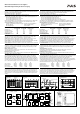
Output characteristic (see Fig. 2)
The curve in this figure is a typical curve for 24V unit. The other output voltages have an
equivalent and proportional performance.
BonusPower
®
time (see Fig. 3)
The curve in this figure shows the duration until the output voltage starts dipping when more
than 480W is drawn (controlled by software).
Ausgangs- und Überlastverhalten
Die Geräte sind leerlauf-, überlast- und kurzschlussfest und sind zur Versorgung von Lasten mit
einem Dauerleistungsbedarf bis zu 480W und einem kurzzeitigem Leistungsbedarf bis 720W
konstruiert.
Ausgangskennlinie (siehe Bild 2)
Die Kennlinie in diesem Bild ist die Kennlinie eines typischen 24V Gerätes. Die anderen
A
usgangsspannungen zeigen ein proportional vergleichbares Verhalten.
BonusPower
®
Zeit (siehe Bild 3)
Die Kennlinie in diesem Bild gibt die Dauer an bis die Ausgangsspannung sinkt, wenn mehr als
480W entnommen werden (softwaregesteuert).
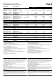
Dielectric Strength (see Fig. 5)
The output voltage is floating and separated from the input according to SELV (IEC/EN
60950-1) and PELV (EN 60204-1, EN 50178; IEC 62103, IEC 60364-4-41) requirements.
Type and factory tests are conducted by the manufacturer. Field tests may be conducted in
the field using the appropriate test equipment which applies the voltage with a slow ramp (2s
up and 2s down). Connect all phase-terminals together as well as all output poles before the
test is conducted. When testing, set the cut-off current settings to the value in the table below.
A B C D
Type Test (60s) 2500Vac 3000Vac 500Vac 500Vac
Factory Test (5s) 2500Vac 2500Vac 500Vac 500Vac
Field Test (5s) 2000Vac 2000Vac 500Vac 500Vac
Cut-off current setting > 10mA > 10mA > 30mA > 1mA
Isolationsfestigkeit (siehe Bild 5)
Die Ausgangsspannung hat keinen Bezug zur Erde oder Schutzleiter und ist zum Eingang nach den
SELV (IEC/EN 60950-1) und PELV (EN 60204-1, EN 50178, IEC 62103, IEC 60364-4-41)
Standards getrennt. Typ- und Stückprüfungen werden beim Hersteller durchgeführt.
Wiederholungsprüfungen dürfen mittels geeigneten Prüfgenerators mit langsam (2s) ansteigenden
und abfallenden Spannungsrampen in der Anwendung erfolgen. Vor den Tests sind alle Phasen wie
auch alle Ausgangspole miteinander zu verbinden. Während der Tests darf die Strom-
A
bschaltschwelle nicht kleiner als der in der Liste angegebene Wert sein.
A B C D
Typprüfung (60s) 2500Vac 3000Vac 500Vac 500Vac
Stückprüfung (5s) 2500Vac 2500Vac 500Vac 500Vac
Wiederholungsprüfung (5s) 2000Vac 2000Vac 500Vac 500Vac
Strom- Abschaltschwelle > 10mA > 10mA > 30mA > 1mA
Operation on 2-Phases (see Fig. 4)
No external protection device is required to protect against a phase-loss failure. The power
supply is allowed to run permanently on two phases, when the de-rating requirements are
fulfilled. A long-term exceeding of the de-rating limits will result in a thermal shut-down of the
unit. During power-on, some start-up attempts can occur until a permanent output power is
available.
Betrieb an 2-Phasen (siehe Bild 4)
Es ist kein externer Schutz gegen Ausfall einer Phase erforderlich. Die Stromversorgung darf
dauerhaft an 2 Phasen betrieben werden, wenn die Ausgangsleistung bei höheren Temperaturen
reduziert wird. Eine dauerhafte Überschreitung dieses Grenzwertes kann zu einer thermischen
A
bschaltung des Gerätes führen. Beim Einschalten der Netzspannung kann es zu mehreren
Startversuchen kommen, bevor das Gerät dauerhaft Ausgangsleistung liefert.
Fig. 1 / Bild 1
Output Characteristic /Ausgangskennlinie
Fig. 2 / Bild 2
BonusPower
®
Time / Zeit
Fig. 3 / Bild 3
DC-OK-Signal
Fig. 4 / Bild 4
2-Phase Operation / 2-Phasenbetrieb
Output Voltage
0
0 5 10 20 25
4
8
12
28V
16
20
24
35
A
15 30
Output Current
s
h
o
r
t
-
t
e
r
m
Adjustment
Range
c
o
n
t
i
n
u
o
u
s
m
a
x
.
Bonus Time
0
110 120 130 140 150
160%
Output Power
1
2
3
4
5s
m
i
n
.
250ms
90% V
ADJ
<1ms
10%
open
V
OUT
=
V
ADJ
openclosed closed
>1ms
Allowed Output Power
0
-25 0 20
70°C
25%
50%
75%
100%
125%
150%
c
o
n
t
i
n
u
o
u
s
Ambient Temperature
f
o
r
t
y
p
.
4
s
40 60
A
.
.
.
2
x
4
6
0
t
o
5
5
2
V
a
c
B
.
.
.
2
x
3
4
0
t
o
4
6
0
V
a
c
B
A
Fig. 5 / Bild 5
Insulation / Isolation
Fig. 6 / Bild 6
Functional Diagram / Funktionsschaltbild
Fig. 7 / Bild 7
Physical Dimensions / Abmessungen
A
D
C
B
B
L1
Input DC-ok
Earth
Output
-
+
L3
L2
+
+
-
-
V
OUT
DC-ok
Contact
Output
Over-
Voltage
Protection
PFC
Converter
Input Filter
Input Rectifier
Inrush Limiter
Transient Filter
Output
Voltage
Regulator
Power
Converter
Output
Filter
DC ok
Relay
Output
Voltage
Monitor
Output
Power
Manager
Temper-
ature
Shut-
down
Overload
LED
DC-ok
LED
L2
L3
L1
PU-347.010.00-10C