
Data Sheet

QT20.241, QT20.241-C1
Q-Series
24V, 20A, THREE PHASE INPUT
Apr. 2017 / Rev. 2.1 DS-QT20.241-EN
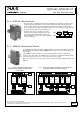
22.6. OUTPUT CIRCUIT BREAKERS
Standard miniature circuit breakers (MCB’s or UL1077 circuit breakers) are commonly used for AC-supply systems and
may also be used on DC branches.
MCB’s are designed to protect wires and circuits. If the ampere value and the characteristics of the MCB are adapted to
the wire size that is used, the wiring is considered as thermally safe regardless of whether the MCB opens or not.
To avoid voltage dips and under-voltage situations in adjacent 24V branches which are supplied by the same source, a
fast (magnetic) tripping of the MCB is desired. A quick shutdown within 10ms is necessary corresponding roughly to
the ride-through time of PLC's. This requires power supplies with high current reserves and large output capacitors.
Furthermore, the impedance of the faulty branch must be sufficiently small in order for the current to actually flow.
The best current reserve in the power supply does not help if Ohm’s law does not permit current flow. The following
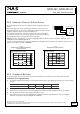
table has typical test results showing which B- and C-Characteristic MCBs magnetically trip depending on the wire cross
section and wire length.
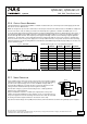
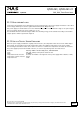
Fig. 22-7 Test circuit
Maximal wire length
*)
for a fast (magnetic) tripping:
0.75mm² 1.0mm² 1.5mm² 2.5mm²
C-2A
29m 39m 56m 86m
C-3A
26m 34m 49m 76m
C-4A
16m 21m 29m 46m
C-6A
3m 5m 7m 8m
C-8A
1m 2m 2m 3m
C-10A
1m 1m 1m 1m
B-6A
18m 23m 31m 54m
B-10A
4m 6m 7m 13m
B-13A
3m 5m 6m 11m
MCB
Power Supply
AC
+
DC
-
+
-
Load
B-16A
1m 1m 1m 2m
24/27
Wire length
S1... Fault simulation switch
S1
*) Don’t forget to consider twice the distance to the load (or cable length) when calculating the total wire length (+ and – wire).
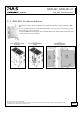
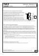
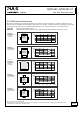
22.7. SERIES OPERATION
Power supplies of the same type can be connected in series for higher output
voltages. It is possible to connect as many units in series as needed, providing
the sum of the output voltage does not exceed 150Vdc. Voltages with a
potential above 60Vdc are not SELV any more and can be dangerous. Such
voltages must be installed with a protection against touching.
Unit B
-
+
Load
+
-
AC
DC
AC
DC
-
+
Unit A
Avoid return voltage (e.g. from a decelerating motor or battery) which is
applied to the output terminals.
Keep an installation clearance of 15mm (left / right) between two power
supplies and avoid installing the power supplies on top of each other. Do not
use power supplies in series in mounting orientations other than the standard
mounting orientation (input terminals on the bottom of the unit).
Pay attention that leakage current, EMI, inrush current, harmonics will increase when using multiple power supplies.
All parameters are typical values specified at 24V, 20A, 3x 400Vac, 50Hz, symmetrical mains voltages, 25°C ambient and after
a 5 minutes run-in time unless otherwise noted.
www.pulspower.com Phone +49 89 9278 0 Germany