
Data Sheet

QT20.241, QT20.241-C1
Q-Series
24V, 20A, THREE PHASE INPUT
Apr. 2017 / Rev. 2.1 DS-QT20.241-EN
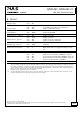
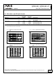
10. LIFETIME EXPECTANCY AND MTBF
3AC 400V 3AC 480V
Calculated lifetime expectancy*) 495 000h
*)
485 000h
*)
At 24V, 10A and 25°C
175 000h
*)
171 000h
*)
At 24V, 10A and 40°C
297 000h
*)
299 000h
*)
At 24V, 20A and 25°C
105 000h 106 000h At 24V, 20A and 40°C
MTBF**) SN 29500, IEC 61709 1 194 000h 1 159 000h At 24V, 20A and 25°C
690 000h 670 000h At 24V, 20A and 40°C
MTBF**) MIL HDBK 217F 389 000h 371 000h At 24V, 20A and 25°C; Ground Benign GB25
284 000h 271 000h At 24V, 20A and 40°C; Ground Benign GB40
*) The calculated lifetime expectancy shown in the table indicates the minimum operating hours (service life) and is determined by the
lifetime expectancy of the built-in electrolytic capacitors. Lifetime expectancy is specified in operational hours and is calculated according
to the capacitor’s manufacturer specification. The manufacturer of the electrolytic capacitors only guarantees a maximum life of up to 15
years (131 400h). Any number exceeding this value is a calculated theoretical lifetime which can be used to compare devices.
**) MTBF stands for Mean Time Between Failure, which is calculated according to statistical device failures, and indicates reliability of a
device. It is the statistical representation of the likelihood of a unit to fail and does not necessarily represent the life of a product.
The MTBF figure is a statistical representation of the likelihood of a device to fail. A MTBF figure of e.g. 1 000 000h means that
statistically one unit will fail every 100 hours if 10 000 units are installed in the field. However, it can not be determined if the failed unit
has been running for 50 000h or only for 100h.
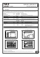
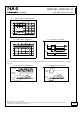
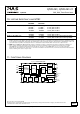
11. FUNCTIONAL DIAGRAM
Fig. 11-1 Functional diagram
+
+
-
-
V
OUT
DC-ok
Contact
Output
Over-
Voltage
PFC
Converter
Protection
Input Filter
Input Rectifier
Inrush Limiter
Transient Filter
Output
Voltage
Regulator
Power
Converter
Output
Filter
DC ok
Relay
Output
Voltage
Monitor
Output
Power
Manager
Temper-
ature
Shut-
down
Overload
LED
DC-ok
LED
L2
L3
L1
10/27
All parameters are typical values specified at 24V, 20A, 3x 400Vac, 50Hz, symmetrical mains voltages, 25°C ambient and after
a 5 minutes run-in time unless otherwise noted.
www.pulspower.com Phone +49 89 9278 0 Germany