
Datasheet
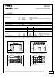
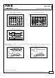
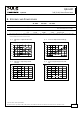
Table Of Contents
- 1. Intended Use
- 2. Installation Requirements
- 3. AC-Input
- 4. DC-Input
- 5. Input Inrush Current
- 6. Output
- 7. Hold-up Time
- 8. Efficiency and Power Losses
- 9. Reliability
- 10. Functional Diagram
- 11. Terminals and Wiring
- 12. Front Side and User Elements
- 13. EMC
- 14. Environment
- 15. Protection Features
- 16. Safety Features
- 17. Dielectric Strength
- 18. Approvals
- 19. Fulfilled Standards
- 20. Used Substances
- 21. Physical Dimensions and Weight
- 22. Accessories
- 23. Application Notes
- 23.1. Repetitive Pulse Loading
- 23.2. Peak Current Capability
- 23.3. Back-feeding Loads
- 23.4. External Input Protection
- 23.5. Charging of Batteries
- Parallel Use to Increase Output Power
- Parallel Use for Redundancy
- 23.8. Daisy Chaining of Outputs
- Series Operation
- 23.10. Inductive and Capacitive Loads
- Operation on Two Phases
- 23.12. Use in a Tightly Sealed Enclosure
- 23.13. Mounting Orientations
QS3.241
Q-Series
24V, 3.4A, SINGLE PHASE INPUT
3. AC-INPUT
AC input nom. AC 100-240V suitable for TN-, TT- and IT mains networks
AC input range min. 85-276Vac continuous operation
min. 60-85Vac full power for 200ms, no damage between 0 and 85Vac
min. 276-300Vac < 500ms
Allowed voltage L or N to earth max. 276Vac continuous, IEC 62103
Input frequency nom. 50–60Hz ±6%
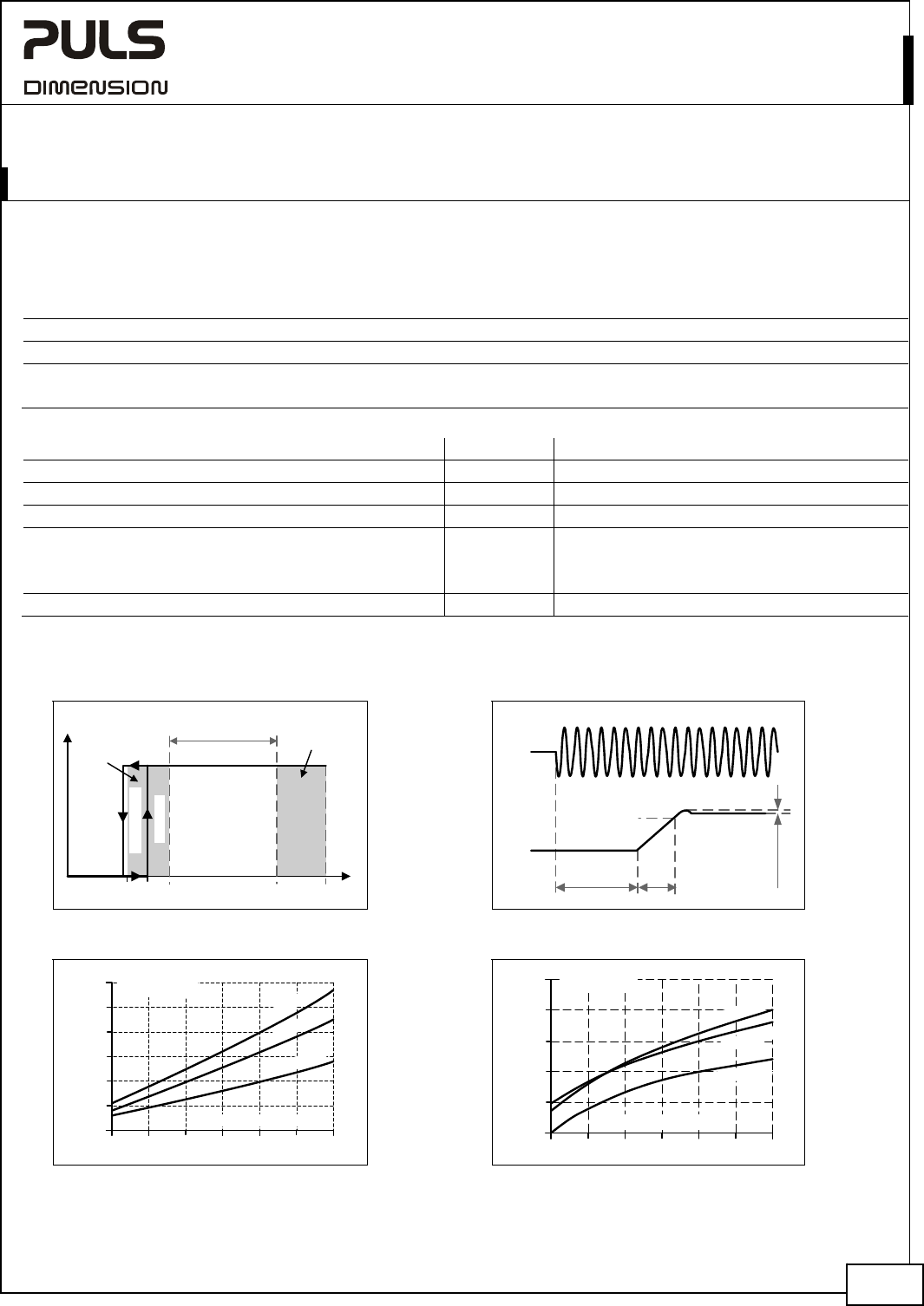
Turn-on voltage typ. 61Vac steady-state value, see Fig. 3-1
Shut-down voltage typ. 58Vac steady-state value, see Fig. 3-1
AC 100V AC 120V AC 230V
Input current typ. 1.67A 1.42A 0.82A at 24V, 3.4A, see Fig. 3-3
Power factor *) typ. 0.55 0.53 0.47 at 24V, 3.4A, see Fig. 3-4
Crest factor **) typ. 3.33 3.9 3.88 at 24V, 3.4A
Start-up delay typ. 360ms 350ms 330ms see Fig. 3-2
Rise time typ. 6ms 5ms 7ms 0mF, 24V, 3.4A, see Fig. 3-2
typ. 20ms 20ms 22ms 3.4mF, 24V, 3.4A, see Fig. 3-2
Turn-on overshoot max. 100mV 100mV 100mV see Fig. 3-2
*) The power factor is the ratio of the true (or real) power to the apparent power in an AC circuit.
**) The crest factor is the mathematical ratio of the peak value to RMS value of the input current waveform.
Fig. 3-1 Input voltage range Fig. 3-2 Turn-on behavior, definitions
Turn-on
85V
Rated
input range
max.
500ms
V
IN
P
OUT
4/25
60V 300Vac276V
Shut-down
full
power
for
200ms
Start-up
delay
Rise
Time
Overshoot
- 5%
Output
Voltage
Input
Voltage
Fig. 3-3 Input current vs. output load at 24V Fig. 3-4 Power factor vs. output load
0.5 1.51.0 2.0 2.5 3.0 3.5A
0
0.3
0.6
0.9
1.2
1.5
1.8A
Output Current
Input
Current, typ.
2
3
0
Va
c
1
2
0
Va
c
100V
a
c
Power
Factor, typ.
0.5 1.0 1.5 2.0 3.5
A
0.35
0.4
0.45
0.5
0.55
0.6
Output Current
12
0Vac
2
3
0
V
a
c
2.5 3.0
1
0
0
V
a
c
Sep. 2017 / Rev. 2.2 DS-QS3.241-EN
All parameters are specified at 24V, 3.4A, 230Vac, 25°C ambient and after a 5 minutes run-in time unless otherwise noted.
www.pulspower.com Phone +49 89 9278 0 Germany