
Data Sheet
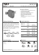


MLY02.100
MiniLine
MLY-Series
DC12-48V, 10A, DUAL REDUNDANCY MODULE
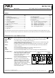
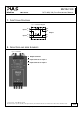
3. INPUT AND OUTPUT CHARACTERISTICS
Number of inputs - 2
Number of outputs - 1
Input voltage nom. DC 12-48V ±25%
The input circuitry must meet the SELV requirements
stipulated by IEC/EN/UL 60950-1.
Input voltage range - 9–60Vdc
Voltage drop, input to output typ. 0.8V at 2x2.5A, see Fig. 3-1
typ. 0.9V at 1x5A, see Fig. 3-2
typ. 0.9V at 2x5A, see Fig. 3-1
Input current nom. 2x 0–5A continuous
nom. 1x 0–10A continuous, see note 1
nom. 2x 5–8A for 5 seconds
Peak input current max. 125A for maximal 10ms per input
Output current nom. 10A continuous
nom. 10–16A for 5 seconds
max.
16A at continuous overload or short circuit, see note 2
Reverse current max. 0.6mA per input, -40°C to +60°C
Reverse voltage max. 200Vdc voltage applied to the output, continuously allowed
Note 1: Each input can be loaded up to 10A. At currents above 10A, the other input should not be loaded. It is preferable to parallel the two
inputs in order to minimize the power loss in such cases.
Note 2: Ensure that the continuous output current does not exceed 16A. Check the short-circuit current of the power sources and if the
power source can deliver more than 16A together, use an appropriate fuse on the output.
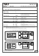
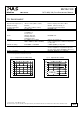
Fig. 3-1 Input to output voltage drop when both inputs draw current
(typical 1+1 redundant case, when the output voltages of the two units are equal or set into “parallel use” mode)
Voltage Drop, typ.
0A 2A 4A 8A
200mV
400mV
600mV
800mV
1000mV
10
A
6A
Input, Output Current
0mV
Output:
2x2A2x1A
4/15
Input:
2x4A2x3A0A 2x5
A
A... 25°C
B... 60°C
A
B
V
A
QS5.241
24V,5A
+
-
QS5.241
24V,5A
+
-
V
A
I
1
I
2
U
1
U
2
Output
I
1
I
2
=
U
2
U
1
= Voltage Drop
U
1
=
U
OUT
-
A
V
I
OUT
U
OUT
Variable
Load,
0-10A
MLY02.100
Input 1
Input 2
Output
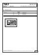
Fig. 3-2 Input to output voltage drop when only one input draws current
Voltage Drop, typ.
0A 2A 4A 8A
200mV
400mV
600mV
800mV
1000mV
6A
10
A
Output Current
0mV
A... 25°C
B... 60°C
A
B
Voltage Drop
U
1
=
U
OUT
-
Not used or
power supply
with lower
voltage
V
A
QS10.241
24V,10A
+
-
I
1
U
1
Output
A
V
I
OUT
U
OUT
Variable
Load,
0-10A
Input 1
Input 2
Output
MLY02.100
Oct. 2010 / Rev. 1.0 DS-MLY02.100-EN
All parameters are specified at 24V, 10A output current, 25°C ambient and after a 5 minutes run-in time unless otherwise noted
www.pulspower.com Phone +49 89 9278 0 Germany