
Data Sheet


MLY02.100
MiniLine
MLY-Series
DC12-48V, 10A, DUAL REDUNDANCY MODULE
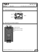
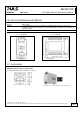
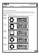
18.4. EXAMPLE: N+1 REDUNDANCY
N+1 Redundancy up to 6.3A requires four ML50.100 power supplies (each 2.1A output current) and two MLY02.100
redundancy modules.
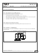
Fig. 18-2 Wiring diagram, N+1 Redundancy, 6.3A output current
14/15
L
N
I
ML50.100
Power
Supply
L N
Input
Output
+ +
- -
DC
OK
ML50.100
Power
Supply
L N
Output
Input
+ +
- -
DC
OK
MLY02.100
IN 1
+
-
+
-
Output
+
- -
IN 2
+
Alarm
Monitor
Load
+
-
ML50.100
Power
Supply
L N
Input
Output
+ +
- -
DC
OK
ML50.100
Power
Supply
L N
Output
Input
+ +
- -
DC
OK
MLY02.100
IN 1
+
-
+
-
Output
+
- -
IN 2
+
II I
Note: Use separate mains systems for each power supply whenever it is possible
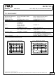
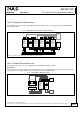
18.5. EXAMPLE: BATTERY BACK-UP
A battery back-up requires one power supply and one MLY02.100 redundancy module.
Please note:
Set output voltage of power supply to 26.5Vdc minimum to ensure, that the load current is delivered from the power
supply and not from charger (battery). Use a fuse between battery and MLY02.100!
Fig. 18-3 Wiring diagram, 10A Battery back-up
24V Battery
I
L
N
PE
Battery
Charger
+
-
Failure
Monitor
Load
ML50.100
Power
Supply
L N
Input
Output
+ +
- -
DC
OK
MLY02.100
IN 1
+
-
+
-
Output
+
- -
+
IN 2
Oct. 2010 / Rev. 1.0 DS-MLY02.100-EN
All parameters are specified at 24V, 10A output current, 25°C ambient and after a 5 minutes run-in time unless otherwise noted
www.pulspower.com Phone +49 89 9278 0 Germany