
User Manual

EN ML60.121 Installation Manual
Product Description
The ML60.121 is a DIN-rail mountable single-phase-input power supply, which provides a floating,
stabilized and galvanically separated SELV/PELV output voltage.
The output of the device fulfils the requirements for a limited power source according to NEC Class
2.
Intended Use
This device is designed for installation in an enclosure and is intended for commercial use, such as
in industrial control, process control, monitoring and measurement equipment or the like. Do not use
this device in equipment where malfunction may cause severe personal injury or threaten human
life.
Installation Instructions
Install device in an enclosure providing protection against electrical, mechanical and fire hazards.
Install the device onto a DIN-rail according to EN 60715 with the input terminals on the bottom of the
device. Other mounting orientations require a reduction in output current.
Make sure that the wiring is correct by following all local and national codes. Use appropriate copper
cables that are designed for a minimum operating temperature of 60°C for ambient temperatures up
to +45°C, 75°C for ambient temperatures up to +60°C and 90°C for ambient temperatures up to
+70°C. Ensure that all strands of a stranded wire enter the terminal connection.
Unused screw terminals should be securely tightened.
The device is designed for pollution degree 2 areas in controlled environments. No condensation or
frost is allowed.
The housing of the device provides a degree of protection of IP20. The housing does not provide
protection against spilled liquids.
The isolation of the device is designed to withstand impulse voltages of overvoltage category III
according to IEC 60664-1.
The device is designed as “Class of Protection” I equipment according to IEC 61140.
Do not use without a proper PE (Protective Earth) connection.
The device is suitable to be supplied from TN, TT and IT mains networks. The voltage between the
L or N terminal and the PE terminal must not exceed 300Vac continuously.
The input can also be powered from batteries or similar DC sources. The voltage between the input
terminals and ground must not exceed 375Vdc continuously.
A disconnecting means shall be provided for the input of the device.
The device is designed for convection cooling and does not require an external fan. Do not obstruct
airflow and do not cover ventilation grid!
The device is designed for altitudes up to 6000m (19685ft). See additional requirements in the
product datasheet for use above 2000m (6560ft).
Keep the following minimum installation clearances: 40mm on top, 20mm on the bottom, 0mm left
and right side. Increase the 0mm to 15mm in case the adjacent device is a heat source.
The device is designed, tested and approved for branch circuits up to 20A without additional
protection device. If an external fuse is utilized, do not use circuit breakers smaller than 10A B- or
6A C-Characteristic to avoid a nuisance tripping of the circuit breaker.
The maximum surrounding air temperature is +70°C (+158°F). The operational temperature is the
same as the ambient or surrounding air temperature and is defined 2cm below the device.
The device is designed to operate in areas between 5% and 95% relative humidity.
Installation Instructions for Hazardous Location Areas
The device is suitable for use in Class I Division 2 Groups A, B, C, D locations.
Substitution of components may impair suitability for this environment.
Do not disconnect the device or operate the voltage adjustment unless power has been switched off
or the area is known to be non-hazardous.
Functional Description
The output is electronically protected against no-load, overload and short circuit and can supply any
kind of loads, including inductive loads and capacitive loads.
Do not apply return voltages from the load to the output terminals higher than 25V.
The output voltage can be adjusted with a small flat-blade screwdriver on the front of the unit.
The green DC-OK LED reports a voltage on the output terminals above 9V.
Devices can be paralleled to increase the output power. The ambient temperature is not allowed to
exceed +45°C. The output voltage shall be adjusted to the same value (±100mV) with the same load
conditions on all devices, or the devices can be left with the factory settings. If more than three
devices are connected in parallel, a diode, fuse or circuit breaker with a rating of 6A or 8A is
required on each output.
Same devices can be connected in series for higher output voltages. It is allowed to connect as
many outputs in series as needed, providing the sum of the output voltage does not exceed 150Vdc.
In case of an internal defect, a redundant circuit limits the maximum output voltage to 19V. The
output shuts down. Cycle input power to restart.
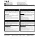
Technical Data
All values are typical figures specified at 230Vac, 50Hz input
voltage, 12V 4.5A output load, 25°C ambient temperature and
after a 5 minutes run-in time unless otherwise noted.
Output voltage
DC 12V Nominal
Adjustment range
12 – 15Vdc Factory setting 12V
Output current
4.5 – 3.6A Below +60°C ambient
3.4 – 2.7A At +70°C ambient
Derate linearly between +60°C and +70°C
Input voltage AC
AC 100 – 240V -15% / +10%
Mains frequency
50 – 60Hz ±6%
Input current AC
0.91 / 0.54A At 120 / 230Vac
Power factor
0.58 / 0.5 At 120 / 230Vac
Input voltage DC
DC 110-300V -20% / +25%
Input current DC
0.57 / 0.2A At 110 / 300Vdc
Input inrush current
16 / 32A pk At 40°C, 120 / 230Vac
Efficiency
85.3 / 87.2% At 120 / 230Vac
Power losses
9.3 / 7.9W At 120 / 230Vac
Hold-up time
25 / 113ms At 120 / 230Vac
Temperature range
-10 to +70°C
Max. wire size (litz wire)
4mm²
Wire size AWG
AWG 20-10
Max. wire diameter
2.8mm
Wire stripping length
7mm / 0.28inch
Tightening torque
1Nm / 9lb.inch
Size (wxhxd)
45x75x91mm Without DIN-rail
Weight
250g / 0.55lb
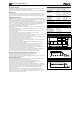
Functional Diagram
Input
Fuse
&
Input
Filter
L
N
Output Over-
Voltage
Protection
Input
Rectifier
&
Inrush
Limiter
Output
Voltage
Regulator
+
+
-
-
Output
Filter
V
OUT
DC-ok
LED
Power
Converter
Output Characteristic
Output voltage
8A
12V
Output current
0V
6A0A
Adjustment range
15V
1A 4A2A 3A 5A 7A
A
B
C
A: for AC 230V mains
B: for AC 120V mains
C: for AC 100V mains
Temperature Range
Allowed output current at 12V
Ambient temperature
0A
-10
4.5A
+60 +70°C
3.4A