
Datasheet


Table Of Contents
- 1. Intended Use
- 2. Installation Requirements
- 3. AC-Input
- 4. Input Inrush Current
- 5. Output
- 6. Hold-up Time
- 7. DC-Input
- 8. Efficiency and Power Losses
- 9. Functional Diagram
- 10. Front Side and User Elements
- 11. Terminals and Wiring
- 12. Lifetime Expectancy and MTBF
- 13. EMC
- 14. Environment
- 15. Protection Features
- 16. Safety Features
- 17. Dielectric Strength
- 18. Approvals
- 19. RoHS, REACH and Other Fulfilled Standards
- 20. Physical Dimensions and Weight
- 21. Accessory
- 22. Application Notes
- 22.1. Peak Current Capability
- 22.2. Back-feeding Loads
- 22.3. Charging of Batteries
- 22.4. External Input Protection
- Parallel Use to Increase Output Power
- Parallel Use for Redundancy
- 22.7. Daisy Chaining of Outputs
- 22.8. Inductive and Capacitive Loads
- Series Operation
- Operation on Two Phases
- 22.11. Use Without PE on the Input
- 22.12. Use in a Tightly Sealed Enclosure
- 22.13. Mounting Orientations
ML60.121
MiniLine-2
12V, 4.5A, SINGLE PHASE INPUT
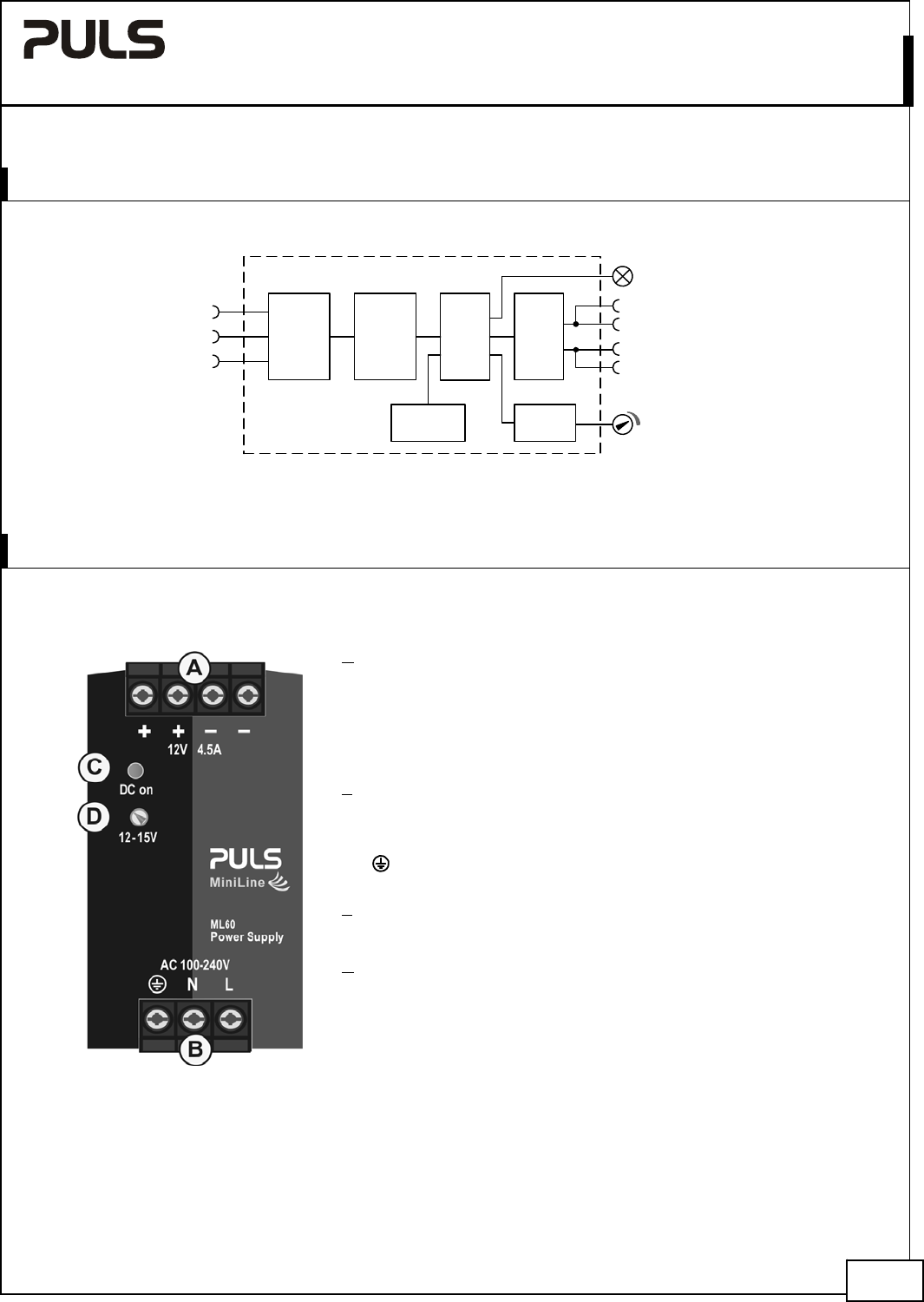
9. FUNCTIONAL DIAGRAM
Fig. 9-1 Functional diagram
Input Fuse
&
Input Filter
L
N
Output Over-
Voltage
Protection
Input
Rectifier
&
NTC
Inrush
Limiter
Power
Converter
Output
Voltage
Regulator
+
-
-
Output
Filter
+
V
OUT
DC
on
PE
10. FRONT SIDE AND USER ELEMENTS
Fig. 10-1 Front side
A
Output Terminals
Screw terminals,
Dual terminals for the negative and positive pole. Both poles are
equal
+ Positive output
- Negative (return) output
B
Input Terminals
Screw terminals
L Phase (Line) input
N Neutral conductor input
PE (Protective Earth) input
C
DC-on LED (green)
On, when the voltage on the output terminals is > 9V
D
Output voltage potentiometer
(single turn potentiometer)
Turn to set the output voltage. Factory set: 12.0V
Nov. 2015 / Rev. 1.4 DS--ML60.121-EN
All parameters are specified at 12V, 4.5A, 230Vac 50Hz input, 25°C ambient and after a 5 minutes run-in time unless otherwise noted.
www.pulspower.com Phone +49 89 9278 0 Germany
9/23