
Datasheet


Table Of Contents
- 1. Intended Use
- 2. Installation Requirements
- 3. AC-Input
- 4. Input Inrush Current
- 5. Output
- 6. Hold-up Time
- 7. DC-Input
- 8. Efficiency and Power Losses
- 9. Functional Diagram
- 10. Front Side and User Elements
- 11. Terminals and Wiring
- 12. Lifetime Expectancy and MTBF
- 13. EMC
- 14. Environment
- 15. Protection Features
- 16. Safety Features
- 17. Dielectric Strength
- 18. Approvals
- 19. RoHS, REACH and Other Fulfilled Standards
- 20. Physical Dimensions and Weight
- 21. Accessory
- 22. Application Notes
- 22.1. Peak Current Capability
- 22.2. Back-feeding Loads
- 22.3. Charging of Batteries
- 22.4. External Input Protection
- Parallel Use to Increase Output Power
- Parallel Use for Redundancy
- 22.7. Daisy Chaining of Outputs
- 22.8. Inductive and Capacitive Loads
- Series Operation
- Operation on Two Phases
- 22.11. Use Without PE on the Input
- 22.12. Use in a Tightly Sealed Enclosure
- 22.13. Mounting Orientations
ML60.121
MiniLine-2
12V, 4.5A, SINGLE PHASE INPUT
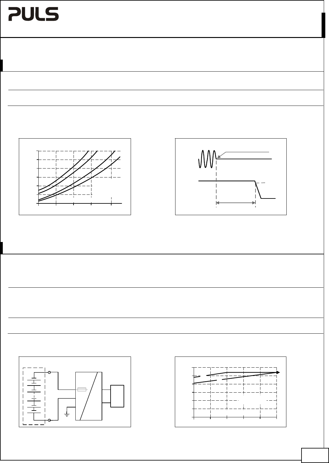
6. HOLD-UP TIME
AC 100V AC 120V AC 230V
Hold-up Time typ. 37ms 56ms 229ms at 12V, 2.25A, see Fig. 6-1
typ. 16ms 25ms 113ms at 12V, 4.5A, see Fig. 6-1
Note: At no load, the hold-up time can be up to several seconds. The green DC-ok lamp is also on during this time
Fig. 6-1 Hold-up time vs. input voltage Fig. 6-2 Shut-down behavior, definitions
0
20
40
100
120ms
85 120 155 190 230Vac
Input Voltage
Hold-up Time
60
80
a) 12V 2.25A typ.
b) 12V 2.25Amin.
c) 12V 4.5A typ.
d) 12V 4.5A min.
a b c
d
- 5%
Hold-up Time
Zero Transition
Output
Voltage
Input
Voltage
7. DC-INPUT
The power supply can also be supplied from a DC source. Use a battery or similar DC source. For other sources contact
PULS. Connect the + pole to L and the – pole to N. Connect the PE terminal to an earth wire or to the machine ground.
DC input nom. DC 110-300V -20%/+25%
DC input range min. 88-375Vdc continuous operation, reduce output power according
Fig. 7-2 at voltages below 130Vdc
Allowed Voltage L/N to Earth max. 375Vdc IEC 62103
DC input current typ. 0.57A / 0.2A 110Vdc / 300Vdc, at 12V, 4.5A
Turn-on voltage typ. 80Vdc steady state value
Shut-down voltage typ. 30-70Vdc depending on output load
Fig. 7-1 Wiring for DC Input
Fig. 7-2 Allowable output current below
110Vdc input voltage
7/23
+
-
Load
L
N
PE
+
-
Power Supply
AC
DC
Battery
internal
fused
0
10
80 90 100 110 130Vdc
20
30
40
60W
Output Power
50
Input Voltage Vdc
(
b
)
(
a
)
(a) Continuous
120
(b) Short-term
Nov. 2015 / Rev. 1.4 DS--ML60.121-EN
All parameters are specified at 12V, 4.5A, 230Vac 50Hz input, 25°C ambient and after a 5 minutes run-in time unless otherwise noted.
www.pulspower.com Phone +49 89 9278 0 Germany